
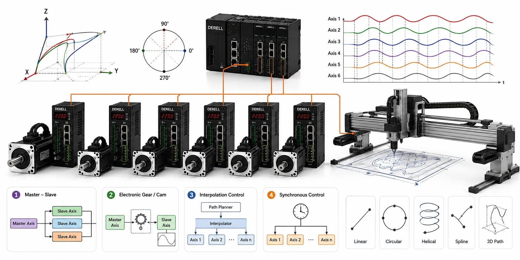
Multi-axis motion control keeps several axes in a defined relationship throughout a move. Starting the motors together is only the first instant. Depending on the machine, the controller may need to maintain a position ratio, phase relationship or shared tool path. A printing cylinder, a flying cutter and an X-Y table need different strategies, even though all use multiple servo-axis components.
Electronic gearing: follow a reference at a fixed ratio
The reference can be a physical axis, an external encoder or a virtual axis generated by the controller. In electronic gearing, a follower command can be written as xB = r × xA + b when both positions use compatible units. r sets the ratio; b sets the position offset. With r = 0.5 and b = 0, A at 40 mm means B at 20 mm; A at 100 mm means B at 50 mm.
Check what “electronic gear” means in the product manual. A drive may also use that term for scaling its pulse-and-direction input: how many command pulses represent one motor revolution. That single-axis conversion does not, by itself, establish a complete master/follower relationship.
Electronic camming: the relationship changes with position
A cam defines follower position as a function of master position: xB = f(xA). A cutter might match a moving product during the cut, then return for the next cycle. A follower can also dwell while its master continues. The cam's slope determines the speed relationship, and changes in that slope affect acceleration demand. Match the profile to the axis's dynamic capability and load and transmission, rather than choosing a curve by appearance.
Interpolation: coordinate the path, not just the endpoints
Interpolation generates axis commands from a geometric path. For a straight move of 100 mm in X and 50 mm in Y, both axes share the same progress along the segment: halfway means X at 50 mm and Y at 25 mm. A circular path needs a changing relationship, so fixed gearing alone cannot generate it. Robotic motion also requires transforming the tool path into joint motion. Velocity, acceleration and jerk limits belong in the planning process.
Clock synchronization gives commands a common execution time
With supported EtherCAT devices, Distributed Clocks aligns local clocks to a common time base. That lets devices sample signals or apply commands at scheduled instants. Real-time performance depends on timing variation and task scheduling as well as the communication cycle period.
Put timing into physical units: at a constant speed of 1 m/s, 1 ms corresponds to 1 mm of travel. This illustrates the effect of a timing mismatch; it is not a prediction of total machine error. Conventional Ethernet and EtherCAT do not offer identical motion behavior. For PROFINET, verify IRT capability and the required synchronous configuration, rather than relying on the protocol name. The controller, network and servo drives must support the chosen operating mode.
Feedback closes each loop; the machine may need another check
Each motor and drive uses position feedback to track its own demand. Two individually controlled axes can still have a relative position error. A gantry driven on both sides needs appropriate monitoring of that difference and a defined response when it exceeds the permitted limit.
Motor-mounted feedback cannot reveal every error caused by backlash or compliance. Some architectures add a linear load-side sensor. When position accuracy is poor, investigate loop tuning, the position loop, couplings and gearbox backlash together. Copying identical gains into both drives does not prove that the mechanics will track identically.
Feedforward improves tracking without replacing feedback
Feedforward adds a control contribution calculated from the planned velocity or acceleration, helping reduce following error. It still needs a sound model and feedback correction. Speed and torque regulation, dynamic modeling and adaptive control address different parts of the problem. Predictive and adaptive approaches can help in suitable applications; they are not prerequisites for every multi-axis machine.
Commission the relationship and measure the result
Verify reference positions, direction, engineering units, ratio and offset first. Check drive configuration, the applicable autotuning procedure, travel limits and the axis group's fault response. Engaging a follower with an already moving master requires a suitable synchronization function; some gearing blocks only permit engagement at standstill.
Start at low speed under safe commissioning conditions. Record commanded and actual positions, following error, relative axis error, torque demand and network timing, then evaluate the machine at its intended load and speed. Include the real-time control task and feedback noise in the investigation. A network connection alone is not evidence of accurate coordination.