
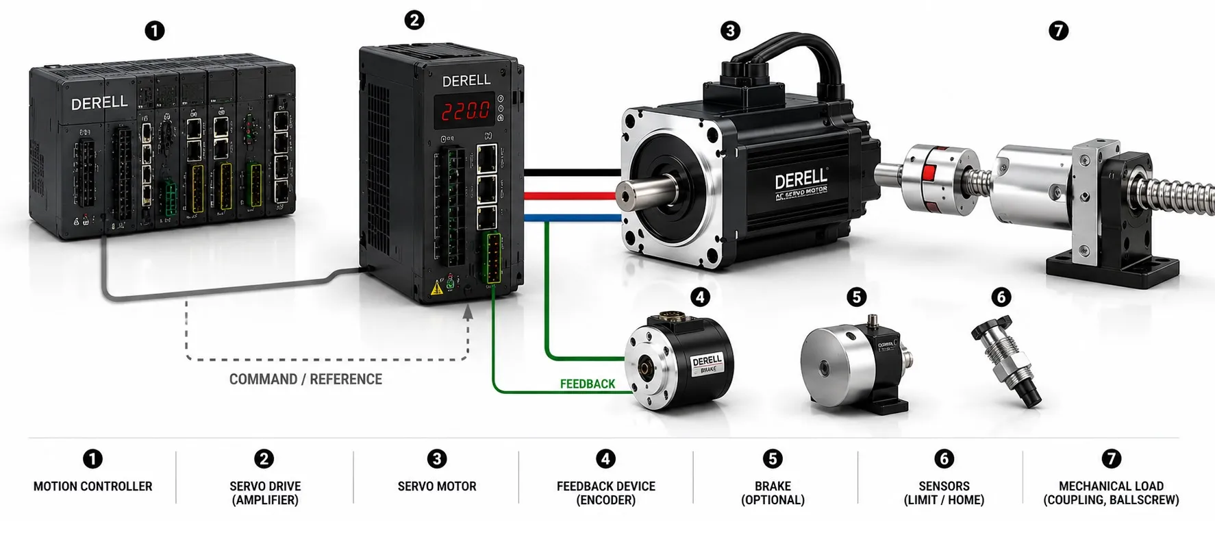
A servo axis combines a motion command, a drive, a motor and feedback with an appropriate power supply and mechanical load. Interfaces, cables and protective equipment connect those functions. The defining feature is closed-loop control: the system measures what happened and uses that information to correct the motion.
Follow the command, then follow the feedback
The controller defines the move
For a slide that must advance 10 mm, the controller determines the motion profile: acceleration, travel and deceleration. A PLC with suitable motion functions, a CNC, an industrial PC or a drive's internal program can perform this job. It can also coordinate multiple axes. An operator panel provides an interface; the HMI is not necessarily the device executing motion control.
Position control and speed or torque control serve different purposes. Their loops may be divided between controller and drive. There is no universal rule that puts every loop in one box or implements the whole axis as a single PID controller.
The drive supplies controlled current
The servo drive turns a command into controlled motor currents through its power electronics. Motor energy comes from the power supply, not from the command signal. Current measurements and feedback allow the drive to regulate its output. The motor converts electrical energy into shaft torque and motion.
Labels such as AC, DC and brushless servo describe overlapping characteristics. For a working pair, check voltage, current, continuous and peak torque, speed and feedback compatibility. A matching connector does not establish compatibility; use the supported motor-and-drive combination and its configuration requirements.
Feedback tells the system what actually moved
An encoder or resolver reports motor position; velocity can be derived from position changes. An encoder does not directly measure torque. The drive normally contains the current sensing used by its current-control loop. Both the feedback's electrical interface and its protocol must be supported.
A motor-mounted sensor cannot directly see backlash or compliance farther along the transmission. Some systems use a linear encoder or another load-side sensor as additional feedback. More encoder counts do not automatically deliver matching accuracy at the workpiece. Axis accuracy also depends on where the measurement is taken.
Power architecture depends on the hardware
Many mains-fed drives contain their own rectifier and DC link. Other drives accept an external DC supply; a multi-axis installation may use a shared supply module and DC bus. The 24 V control or brake supply has a different role from the main motor-power supply.
Deceleration can return energy from the load to the drive. Its handling depends on the drive and the duty cycle: regenerative energy management may require a braking resistor or another solution. An external braking resistor is not a mandatory component of every servo axis.
The transmission sets the relationship to the load
A coupling, planetary gearbox, belt drive or screw can connect the motor to the machine. Direct-drive arrangements may need no separate reduction gearbox. Load and transmission calculations must account for inertia, friction, ratio and backlash. A power rating alone is not enough to size the axis.
Try the arithmetic: a screw with a 5 mm lead advances its slide 5 mm per revolution. With a 1:1 motor-to-screw connection, a 10 mm move requires 10 ÷ 5 = 2 motor revolutions. That is a nominal travel calculation, not an accuracy guarantee. Screw errors, clearance and elastic deflection can change the final load position.
Interfaces and supporting hardware complete the axis
Commands may use pulse and direction, a supported analog interface, EtherCAT or CANopen. Two Ethernet ports do not guarantee a compatible motion-control connection. Check the actual protocol and supported functions; the distinction between EtherCAT and conventional Ethernet matters.
Power and feedback may use separate cables or a manufacturer-supported single-cable arrangement. Protective grounding, shielding and noise control affect reliable operation. A home sensor and travel-limit sensors supplement the axis; they do not replace its servo feedback. A motor holding brake is selected when the load needs holding, not as the normal means of stopping every move.