
What is an optocoupler?
Dear colleagues,
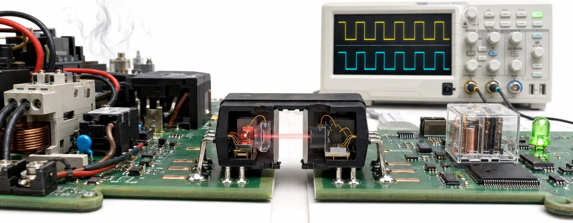
An optocoupler, also called an optoisolator or photocoupler, is an electronic component that transfers a signal between electrically separated circuits using light. It converts an electrical input into light and produces an electrical response on the output side. This allows signals to cross a barrier while maintaining galvanic isolation, provided the surrounding circuit preserves that separation.
What is inside an optocoupler?
The input usually contains an infrared LED. When a suitable forward current flows through it, the LED emits light. An output phototransistor responds by conducting. Other devices use a photodiode with additional circuitry. Although the emitter and detector sit close together, they do not share a metallic signal connection: light carries the signal across an insulating barrier.
An optocoupler should not be treated as a power transfer component. A transformer can transfer energy through magnetic coupling; an optocoupler primarily transfers information. In particular, a phototransistor output needs its own supply and a suitable load connection to produce a useful output voltage.
How are the input and output connected?
The input LED behaves like a diode, with a forward voltage and current limits. A series current limiting resistor is therefore commonly required. Using Ohm's law, a first estimate is R = (Vin − VF) / IF. With a 5 V input, a 1.2 V LED drop and a target current of 5 mA, the result is 760 Ω. An 820 Ω resistor gives approximately 4.6 mA under those assumptions. These are example values; the actual design must account for the data sheet limits, tolerances and resistor power.
Consider a phototransistor whose collector connects to the output supply through a pull-up resistor and whose emitter connects to the output reference. When the LED turns on, the transistor can pull the collector node down. In this arrangement, LED on can mean output LOW, while LED off can mean output HIGH. Light emission does not imply a high logic level in every circuit. Check the DC current and voltage conditions together with the input thresholds of the receiving microcontroller.
How does an optocoupler work?
LED on: light and output conduction are active.
LED off: light stops and phototransistor conduction falls.
600 ms on, 600 ms off; each cycle lasts 1.2 seconds. Red is illustrative; the actual LED is typically infrared. This illustration is not a wiring diagram or a speed measurement.
What is CTR, and why does it matter?
CTR means current transfer ratio. For a phototransistor optocoupler, it is expressed as CTR = (IC / IF) × 100%. An LED current of 5 mA and a CTR of 50% correspond to 2.5 mA of collector current under the specified measurement conditions. That calculation alone does not guarantee saturation or successful load drive. CTR varies with LED current, temperature, collector-emitter voltage and ageing. Start with the guaranteed minimum CTR and its test conditions, rather than assuming the typical value will apply to every device.
Where are optocouplers used, and which type is suitable?
They can separate field signals from control electronics in PLC inputs and sensor interfaces. In industrial communication circuits, signal isolation may also require an isolated supply and a suitable interface design. In switched mode power supplies, optocouplers can carry output feedback to the controller. Their use depends on the circuit: a PLC, sensor or communication device does not necessarily contain one.
Phototransistor output devices are common for general signal transfer. High speed digital types may include an integrated circuit output stage. Optotriacs used to trigger a triac and optical relays with a MOSFET output behave differently. Matching pin counts do not establish interchangeability. When driving a thyristor or another power switch, check the trigger requirements, output structure and the manufacturer's recommended circuit.
What should you check when selecting or testing one?
Input current, output voltage, output current, minimum CTR and switching time are key selection parameters. Propagation delay and common mode transient immunity also matter for high speed devices. Supply decoupling capacitors, board layout and signal references influence the performance of the complete circuit.
Isolation test voltage is not the continuous working voltage. Check the rated working conditions, insulation classification and the board's clearance and creepage distances together. A diode measurement on the input LED in an unpowered circuit can provide an initial clue, but it does not verify CTR, output performance or insulation integrity. Functional testing should use the correct pinout and the low voltage test circuit specified in the data sheet.
This article provides general technical information. Use the manufacturer's data sheet for application specific values and limits.