
What is an inductor?
What is an inductor?
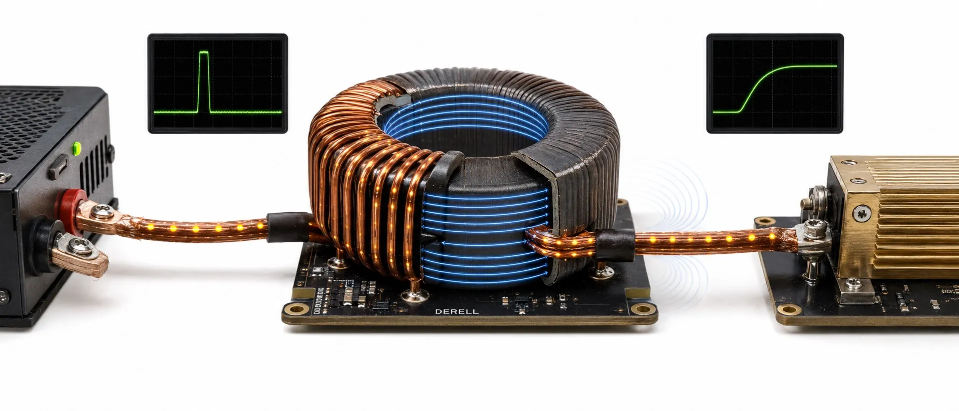
An inductor is a passive electronic component that stores energy in a magnetic field associated with the electric current flowing through it. Often called a coil, it is commonly made from wound conductive wire. Designs include air cores, ferrite cores and other magnetic materials.
Its defining property is that it opposes changes in current. An inductor does not necessarily reduce current; it affects how quickly current can rise or fall. This behaviour is important in power converters, filters, sensors and switched inductive loads.
How does it work? Changing current produces voltage
Current through a coil creates a magnetic field. When that current changes, the magnetic flux linked to the coil changes too, producing a self-induced voltage. Faraday’s and Lenz’s laws explain why this effect acts to oppose the change in current.
For an ideal inductor with constant inductance, taking the terminal where current enters as positive gives vL = L·di/dt. Here vL is the terminal voltage, L is inductance and di/dt is the rate of change of current. Producing the same current change in less time requires a greater voltage.
Quick example: If current in an ideal 1 mH inductor increases steadily by 1 A over 1 ms, vL = 0.001 × (1 / 0.001) = 1 V. When current decreases, the voltage reverses under the same sign convention, allowing the inductor to return stored energy to the circuit.
Inductance and stored energy
Inductance determines the relationship between changing current and induced voltage. Its symbol is L and its unit is the henry (H), named after Joseph Henry. Circuit boards commonly use values in µH and mH: 1 mH = 1,000 µH.
For an ideal linear inductor with constant inductance, stored energy is E = ½LI². A 1 mH inductor carrying 2 A stores 0.002 J = 2 mJ. Doubling current in the same inductor quadruples the stored energy. This simple expression cannot be applied unchanged once core saturation causes L to vary significantly.
Behaviour in DC and AC circuits
In a DC circuit: Inductance affects how current rises after connection. Once current is constant, the ideal inductor’s inductive voltage is zero. A real coil has winding resistance, or DCR, which causes voltage drop and heating. Its continuous DC current is not determined by L alone; the supply and total circuit resistance also matter.
In an AC circuit: An ideal inductor’s inductive reactance in sinusoidal steady state is XL = 2πfL, measured in ohms (Ω). Reactance increases with frequency in the ideal model. For 1 mH, it is approximately 0.314 Ω at 50 Hz and 6.28 Ω at 1 kHz. Current in an ideal inductor lags voltage by 90°.
Reactance is different from resistance that dissipates energy as heat. An ideal inductor receives and returns energy; a real component also has losses. At high frequencies, parasitic capacitance between turns and the core’s properties become important. Above its self-resonant frequency, an inductor can behave capacitively. XL = 2πfL therefore does not describe a real component’s total impedance at every frequency.
Inductor, capacitor and resistor compared
| Component | Basic behaviour | Ideal relationship |
|---|---|---|
| Inductor | Stores magnetic-field energy; opposes changes in current. | v = L·di/dt |
| Capacitor | Stores electric-field energy; opposes changes in voltage. | i = C·dv/dt |
| Resistor | Converts electrical energy into heat. | v = R·i |
Core materials and inductor types
Air-core inductors have no ferromagnetic core saturation and can be used in RF and resonant circuits. Ferrite-core inductors can provide higher inductance in a smaller package within an appropriate frequency range. Iron-powder and metal-composite cores are also used in power circuits; their loss and saturation behaviour depends on the material.
For a power inductor, current capability, temperature and losses are key concerns. For an RF inductor, quality factor and frequency behaviour often matter more. Multilayer, wirewound and magnetically shielded constructions serve different needs. Two inductors with the same µH rating may perform differently in the same circuit.
Where are inductors used?
Power conversion: In buck and boost converters, an inductor receives and releases energy during the switching cycle. In switch-mode power supplies, it works with switching devices such as MOSFETs and control integrated circuits. Combining inductors and capacitors in a suitable design helps reduce output ripple.
Filtering and sensing: Coils are used in filters that suppress unwanted frequency components on power and signal lines. Inductive sensors detect how eddy currents in a metal target affect a coil-based oscillator. Transformers also use magnetic coupling, but their role in transferring energy between circuits distinguishes them from a single inductor.
Why can switching off a coil create a voltage spike?
When current through a relay coil or another inductive load is forced to stop abruptly, the coil attempts to maintain current and its terminal voltage rises. This adds electrical stress to the transistor switching the load.
In DC relay drivers, a correctly oriented flyback diode provides a path for coil current when the switch turns off. A simple diode can make current decay more slowly and delay relay release. Depending on the circuit, a suitable TVS or voltage clamp may be used. The suitability of a varistor likewise depends on voltage, energy and load type.
Which specifications matter when choosing an inductor?
Inductance and tolerance must suit the operating frequency and required current ripple. Saturation current, Isat, corresponds to a manufacturer-defined drop in inductance and must be considered against the application’s peak current. The thermal current rating, Irms, is based on temperature rise under specified test conditions; the actual RMS current, environment and cooling matter. These are different limits.
DCR contributes to copper loss. An approximate winding-loss calculation is P ≈ Irms²·DCR, with additional winding and core losses assessed at high frequency. Self-resonant frequency, temperature range, physical size and magnetic shielding also affect the choice. Matching only the µH value printed on a component is not enough.