
What is a ceramic resonator?
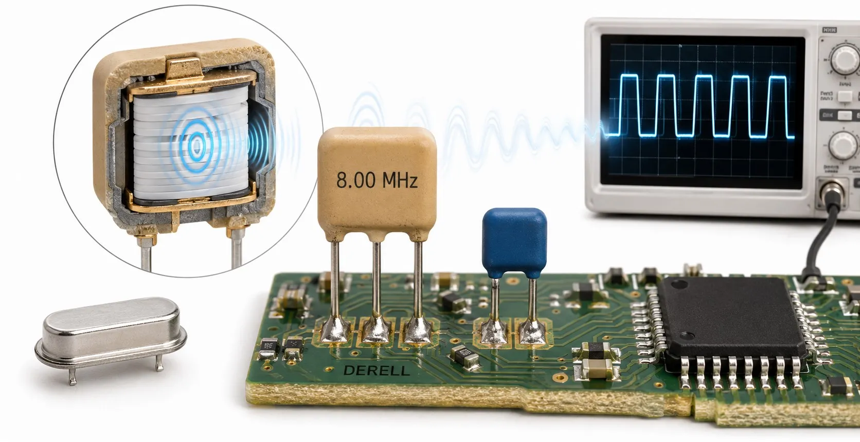
What is a ceramic resonator, and what does it do?
Hello colleagues,
A ceramic resonator is a passive component that uses the mechanical resonance of a piezoelectric ceramic to provide a frequency reference for an electronic circuit. It can form part of the clock circuit that sets the timing of a microcontroller. Here, “clock” means the electrical rhythm used to coordinate operations. Frequency describes how many times that rhythm repeats per second.
A key distinction: A resonator is not a module that produces a clock output simply when power is applied. It needs an active oscillator circuit to sustain oscillation. That circuitry is often built into the integrated circuit. The resonator helps determine the frequency; the amplifier supplies the energy needed to overcome losses.
How does it work?
The piezoelectric effect couples electrical and mechanical behaviour: an electrical stimulus produces deformation, while mechanical stress produces an electrical response. The ceramic element’s material and dimensions support particular vibration modes. With suitable feedback conditions, the circuit oscillates near one of these resonances. This mechanical process differs from the electrical energy exchange between an inductor and a capacitor in an LC circuit.
The active circuit may use a transistor amplifier or a suitable inverting stage. Resistors affect bias and drive conditions, while load capacitors affect the conditions for oscillation. Increasing capacitance arbitrarily is not a reliable improvement: excessive loading can prevent oscillation from starting.
Two-terminal and three-terminal versions
A two-terminal resonator may need external load capacitors, depending on the IC and its recommended circuit. Many three-terminal resonators contain both load capacitors inside the package. In a common arrangement, the outer terminals connect to the oscillator pins and the common terminal connects to circuit ground. However, always confirm the pinout and built-in capacitance in the datasheet; appearance alone is insufficient.
Three terminals do not make a component a ceramic filter. A ceramic resonator provides a frequency reference for an oscillator. A ceramic filter passes a selected frequency band while attenuating other frequencies. Similar packages, colours or terminal counts do not make these components interchangeable.
Ceramic resonator, quartz crystal or oscillator?
A ceramic resonator and a quartz crystal are passive resonant components. A complete oscillator module also contains active circuitry and delivers an output when supplied as specified. Since these names are sometimes used loosely, check whether a part described as a crystal oscillator is a bare crystal or a complete powered module.
Ceramic resonators can offer low cost, compact size and a reduced component count. Quartz crystals generally offer better frequency accuracy and stability. Neither category has one universal tolerance specification. On a microprocessor or microcontroller board, the right choice depends on the application’s permitted total clock error.
An 8 MHz example: what does tolerance mean?
Consider a hypothetical device rated at 8 MHz with an initial frequency tolerance of ±0.5%. The calculation is 8,000,000 × 0.005 = 40,000 Hz. Under the specified reference conditions, its frequency could be between 7.96 and 8.04 MHz. Also, ±0.5% equals ±5,000 ppm. This is an example, not a specification shared by every ceramic resonator.
For comparison, a crystal at the same nominal frequency with an initial tolerance of ±20 ppm would have an initial deviation of ±160 Hz. Actual operating accuracy must also account for temperature variation, aging and circuit loading. Initial tolerance is not the total error across all operating conditions.
Where are ceramic resonators useful?
When their accuracy meets the design requirements, ceramic resonators can serve in appliance controls, remote controls and industrial electronics. For example, a controller might read an input through an optocoupler, operate an LED indicator and switch a load through a MOSFET. The resonator does not drive that load; it provides a timing reference for the controller.
Precision time measurement and communications with tight clock error limits may require a more suitable crystal or oscillator. An RF module may use a frequency reference separate from the controller’s clock. For UART, USB or CAN, the protocol name alone does not settle the choice. Check the IC requirements, data rate, clock generation method and total error budget.
Selection and troubleshooting
When selecting a part, check nominal frequency, initial tolerance, operating temperature, aging limits, built-in capacitors, package and pinout. Confirm the controller’s external resonator support and clock configuration. Keep oscillator connections short and follow the manufacturer’s layout guidance. Shock and vibration performance should also come from the selected part’s specifications rather than a blanket claim about ceramic components.
If the board will not run, first check the controller’s DC supply, reset conditions, clock settings and solder joints. A failed diode in the supply path or a damaged protective varistor can also stop a board from operating. A dead board does not automatically mean a failed resonator.
A multimeter continuity test cannot establish that a resonator works at the correct frequency. Check frequency and waveform using a suitable measurement method, preferably at a buffered clock output if the controller provides one. Probe capacitance can disturb an oscillator node; oscillation stopping when the probe touches it does not by itself prove component failure. Inspect the board with power removed. Before powered measurements, verify isolation and instrument grounding; never connect an earth-grounded oscilloscope probe directly to a mains-referenced board.