
What is a capacitive encoder?
What is a capacitive encoder?
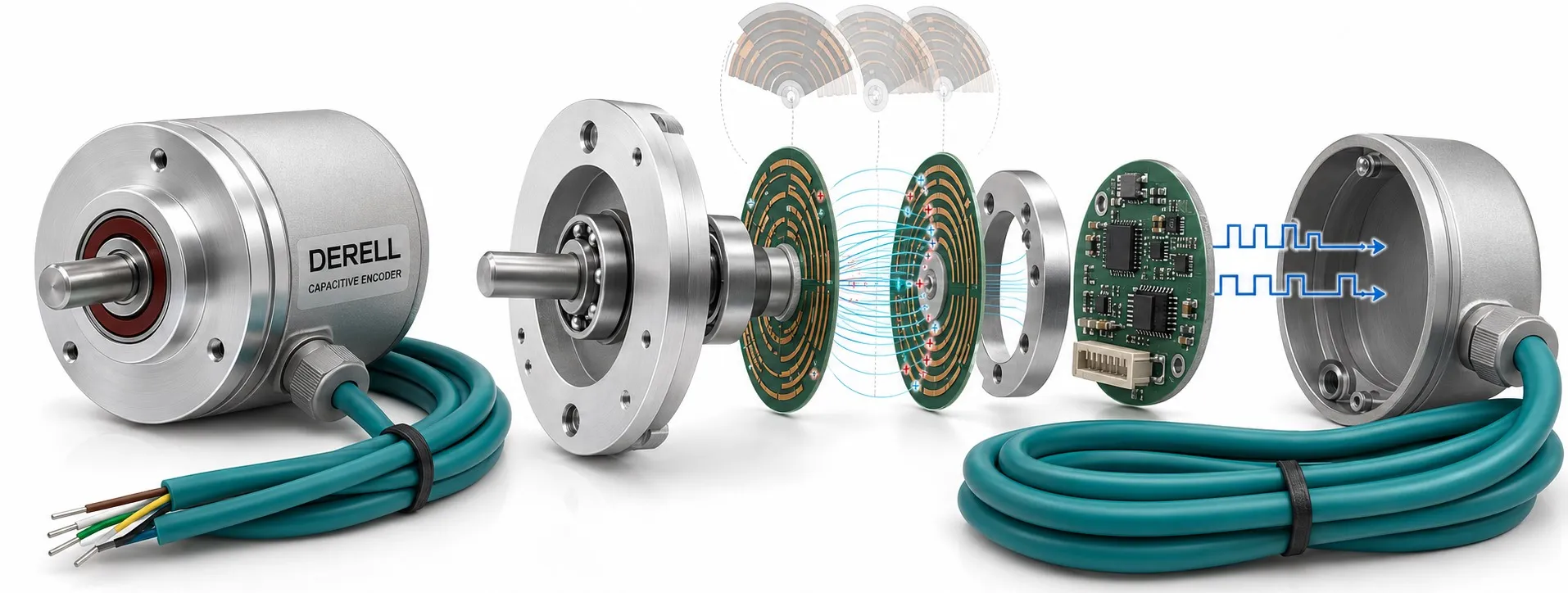
A capacitive encoder measures motion through changes in the capacitive coupling between moving and stationary electrodes. Its electronics turn those changes into position data or pulses from which a controller can determine travel, direction and speed. In a rotary design, a patterned rotor turns with the shaft. The sensing surfaces need no sliding electrical contact.
How an electric field becomes a position measurement
Two conductive surfaces separated by an insulating medium form a capacitive structure. For a simplified parallel-plate example, C ≈ ε × A / d, where A is the overlapping area, d is the gap and ε describes the medium's permittivity. With the gap and medium held constant, more overlap produces more capacitance. This explains the principle; it is not a complete calibration equation for an encoder.
In an AMT-style arrangement, stationary transmitting electrodes generate a high-frequency excitation signal. A pattern on the rotating PCB modulates the coupling. Receiving electrodes and signal-processing electronics extract position from the response. Multiple electrodes, the pattern and the processing algorithm work together, allowing output resolution to differ from a simple count of physical marks.
Does a capacitive proximity sensor do the same job?
A capacitive proximity sensor typically detects whether material is present or a level has been reached. An encoder produces measured motion feedback. Both belong to the capacitive sensing family, but their outputs and intended tasks differ. Do not assume that an encoder connects like an ordinary NPN or PNP switching sensor.
Incremental and absolute capacitive feedback
An incremental encoder provides changes in position, commonly through A/B pulse channels. Their 90-degree electrical phase relationship lets the controller determine direction from the order of transitions. A Z index, when provided, supplies a revolution reference. Which physical direction corresponds to A leading B depends on wiring, configuration and the viewing end of the shaft.
An absolute encoder uses suitable electrode geometry and processing to identify position within its measurement range. Capacitive absolute products may offer SPI, SSI or an RS-485-based interface. Single-turn absolute feedback identifies the angle within one revolution; it does not inherently report the accumulated number of revolutions. For a multiturn product, check what happens to turn tracking when power is removed.
Reading resolution specifications correctly
If the datasheet defines an incremental output as 2,048 complete cycles per channel per revolution, x4 decoding gives 8,192 counts per revolution. The corresponding count step is approximately 360° / 8,192 = 0.0439°. That is not an accuracy specification of ±0.0439°. Resolution describes the reporting increment; accuracy describes how close the measurement is to the true position. Confirm how the manufacturer uses PPR and CPR.
A 12-bit single-turn output has 4,096 possible codes, while a 14-bit output has 16,384. Across a full revolution, the ideal code steps are approximately 0.0879° and 0.0220°. If you change a programmable encoder setting, update the controller's scaling as well.
Resolution also sets the pulse-rate requirement
For P complete channel cycles per revolution, f = P × rpm / 60. At 2,048 cycles per revolution and 1,500 rpm, channel A runs at 51.2 kHz. An x4 decoder processes 204,800 counts per second. An interface's channel-frequency rating and its total counting capacity are not necessarily expressed the same way. Use a suitable high-speed input and check its filtering.
As a product example, the Same Sky AMT10 series offers DIP-switch resolution selection. That feature is not universal to capacitive encoders, and the maximum supported speed may depend on the selected resolution. A simple speed monitor may be sufficient when the requirement is only to detect a stopped or slow-running shaft.
Capacitive, optical and magnetic sensing compared
| Technology | Primary measurement | Items to assess |
|---|---|---|
| Capacitive | Electric-field coupling | Electrode geometry, mounting, environment |
| Optical | Light and a code disc | Optical path, sealing, disc construction |
| Magnetic | Magnetic field | Magnet alignment, gap, external fields |
A Hall effect encoder is one magnetic approach; optical and magnetic encoders each have useful strengths. Capacitive position sensing does not inherently need an optical path or a magnet, although a product may use an additional sensor for an auxiliary function. A resolver uses a different electromagnetic method. The technology name alone does not identify the best device for a machine.
Contamination tolerance and mounting deserve separate checks
Some capacitive designs avoid the problem of oil or dust blocking an optical path. However, contamination tolerance is not a promise of resistance to every liquid. Materials around the sensing structure can affect capacitive coupling. Assess condensation, conductive deposits and cleaning methods against the specific product's environmental limits. An exposed module and a sealed enclosure provide different protection.
A slipping rotor, incorrect axial position or excessive eccentricity can corrupt feedback. Hollow-shaft construction describes the mounting arrangement; a linear encoder describes measurement of straight-line travel. Follow the mounting instructions for spacing and alignment, and choose appropriate cables and fittings from the sensor accessories range.
Connecting and commissioning the encoder
Verify supply voltage, output levels and communication separately. A 5 V logic output may not directly suit a 24 V PLC input. A differential line driver needs a compatible receiver. RS-485 identifies an electrical interface; it does not automatically mean the encoder speaks Modbus. Protocol, framing and timing must match too.
Start by checking direction and counts at low speed. Compare one physical revolution with the expected count, then check for lost pulses as speed rises. An exact factor-of-four error suggests an x1/x4 scaling mismatch; speed-dependent losses point toward bandwidth or filtering. When comparing encoder prices, include the required interface and mounting hardware in the installed cost.
Technical references: Same Sky — capacitive operation and AMT FAQ · Same Sky — encoder technology comparison · Same Sky — AMT10 incremental encoders · Same Sky — absolute capacitive encoders · Beckhoff — encoder input compatibility