
IEC 62196 Explained: EV Connectors, Type 2 and CCS Compatibility
A charging plug can fit a vehicle without providing every charging feature the driver expects. The cable may have a lower current rating, the car may accept fewer phases, or the charging equipment may lack the required communication capability. IEC 62196 provides common requirements for the connection hardware used in conductive EV charging. Understanding its scope helps separate physical compatibility from charging performance.
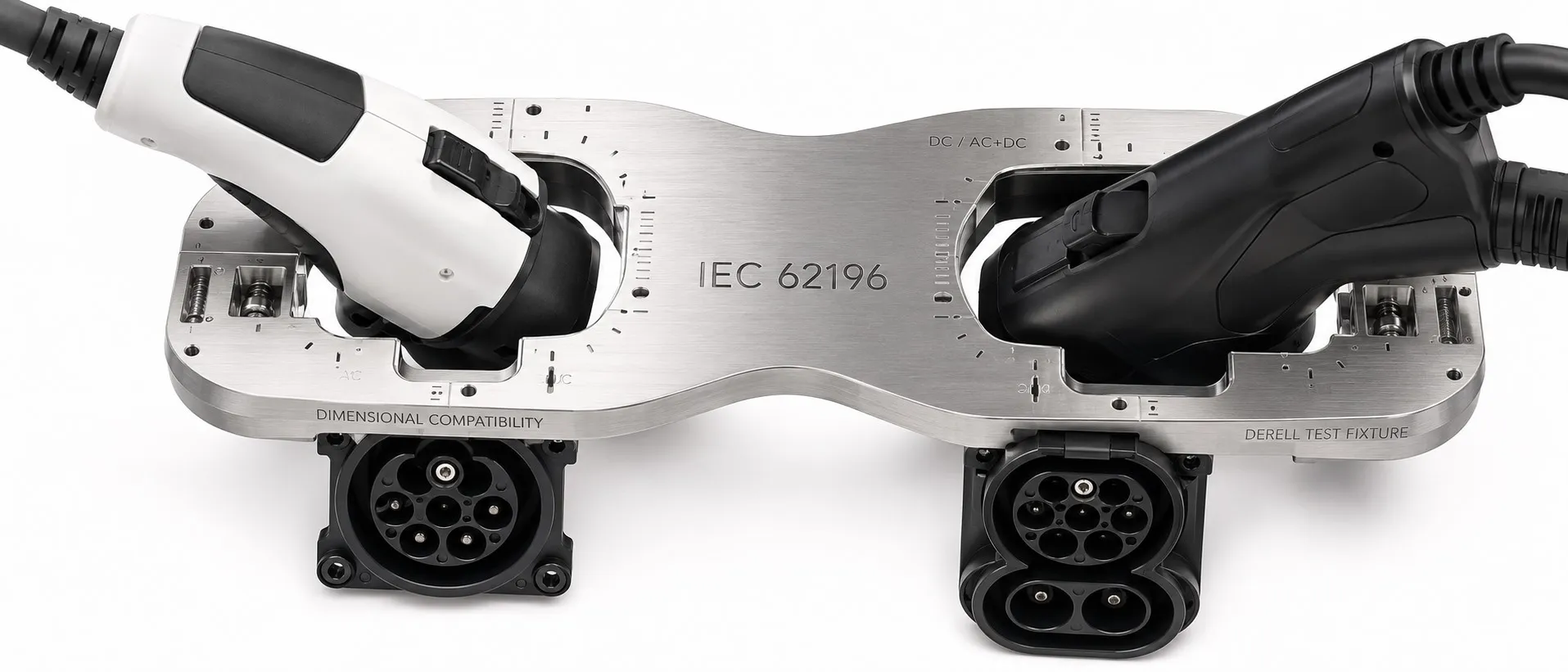
The series covers EV plugs, socket-outlets, vehicle connectors, vehicle inlets and relevant cable assemblies. It includes AC interfaces as well as DC and combined AC/DC connections. “IEC 62196” and “Type 2” are therefore not interchangeable names. Within the wider set of electric vehicle charging standards, this family addresses a specific part of the system.
Three Standards with Different Jobs
IEC 62196 addresses the connection accessories. Its relevant parts establish requirements for the hardware and standardized mating arrangements. IEC 61851 addresses the conductive charging system, including charging modes, control functions and electrical safety requirements.
ISO 15118 deals with higher-level communication between the vehicle and charging equipment. Depending on the implementation, that communication can support automated authorization, charging schedules and bidirectional power transfer. A compliant connector does not automatically add those functions to a vehicle or charging station.
Which IEC 62196 Part Applies?
IEC 62196-1:2025 provides general requirements for the covered accessories and cable assemblies. It is considered alongside the applicable interface-specific part.
IEC 62196-2:2025 addresses dimensional compatibility for AC charging accessories. This is the part commonly encountered when examining Type 1 and Type 2 AC products.
IEC 62196-3:2026 addresses DC and combined AC/DC vehicle couplers. This edition incorporates the former IEC TS 62196-3-1 content as normative Annex AA. The IEC’s corrected publication includes the August 2026 corrigendum.
These are useful starting points rather than an exhaustive catalogue of the series. A procurement specification should identify the applicable part and edition, followed by the required product ratings. A bare reference to “IEC 62196 compliant” leaves too much of the intended application unspecified.
Type 1, Type 2 and CCS2 in Practical Terms
Type 1 is associated with single-phase AC charging and the familiar SAE J1772 interface. A suitable product can reference both SAE J1772 and IEC 62196-2. Those references describe overlapping requirements rather than two incompatible identities.
Type 2 accommodates single-phase or three-phase AC charging when the vehicle, cable and supply equipment support the arrangement. CCS2 uses a combined vehicle inlet with a Type 2-related upper section and two additional large DC power contacts below it. During DC charging, CCS connectors carry the main charging current through those dedicated DC contacts.
A compatible CCS2 vehicle inlet can accept a Type 2 connector for AC charging. An ordinary Type 2 AC cable does not provide the additional DC power connection. The difference between Type 2 and CCS therefore extends beyond the outline of the plug.
The Seven Type 2 Contacts
The Type 2 arrangement provides L1, L2, L3, N and PE power contacts, plus CP and PP signal contacts. The supply arrangement determines which phase conductors are used. PE provides the protective earth connection; it does not serve as the neutral conductor.
Control Pilot, or CP, participates in connection detection and charging control. Basic AC charging can use a PWM signal to advertise the available current limit. Proximity Pilot, or PP, is used with resistance coding to identify a Type 2 cable’s current capability. The coding communicates a limit; it does not operate as an overcurrent protective device.
Why the Same Plug Can Deliver Different Charging Power
Connector shape does not establish charging power. Supply voltage, permitted current and the number of active phases all matter. For a balanced three-phase load, power is approximately √3 × line-to-line voltage × line current × power factor.
Assuming a power factor close to one, 230 V at 32 A single-phase gives about 7.4 kW. At 400 V three-phase, 16 A per phase gives roughly 11 kW, while 32 A per phase gives roughly 22 kW. These are approximate AC input figures.
The unit kilowatt describes power. Comparing 7.4 kW, 11 kW and 22 kW charging equipment requires checking the vehicle’s phase support and onboard charger rating as well as the supply.
For example, a car limited to 11 kW AC will not accept 22 kW merely because the station and cable support it. With AC charging, the onboard charger converts AC to DC. With DC charging, that conversion takes place outside the vehicle. Energy added to the battery is measured in kilowatt-hours; conversion losses mean it will differ from the energy drawn at the supply.
Reading a Cable Specification Properly
Start with the vehicle inlet, its AC charging capability and the station’s connection arrangement. A tethered wallbox already has a vehicle cable; a socketed unit needs an appropriate detachable assembly. For home charging, available installation capacity is another essential constraint.
Then check the cable’s phase configuration, rated current, length, temperature range and environmental rating. An IP rating has conditions. Protection when the connector is mated may differ from protection with a cap fitted or with the contacts exposed. Read the manufacturer’s stated condition rather than treating one IP number as applicable at all times.
Contact condition also matters. Damage or a poor connection can increase contact resistance and local heating. At unchanged resistance, doubling current multiplies I²R heating by four. Cracking, melting, discoloration or abnormal heating calls for taking the affected equipment out of use and having it assessed.
A Connector Standard Does Not Complete the Installation
Protective earthing, fault detection and appropriate circuit protection must work together. The selection of residual-current protection depends on the charging equipment’s DC residual-current detection provisions and the applicable installation requirements. The connector’s standard marking does not establish that the complete installation has been designed correctly.
Likewise, adding an unapproved adapter or extension lead does not resolve an unsuitable cable arrangement. Use the vehicle and equipment manufacturers’ supported connection options.
What to Ask When Checking Compliance
Ask for documentation that identifies the exact product model, applicable standard edition and rated operating conditions. Then check compatibility across the vehicle, cable, station and installation. Mechanical fit, electrical rating and communication support are separate checks. Conductive connector compliance also provides no automatic evidence of suitability for wireless power transfer.
Technical references: IEC 62196-1:2025 · IEC 62196-2:2025 · IEC 62196-3:2026 · IEC 61851-1 · ISO 15118-20 · Texas Instruments EVSE controller reference design · Phoenix Contact Type 2 cable specifications