
CCS connectors
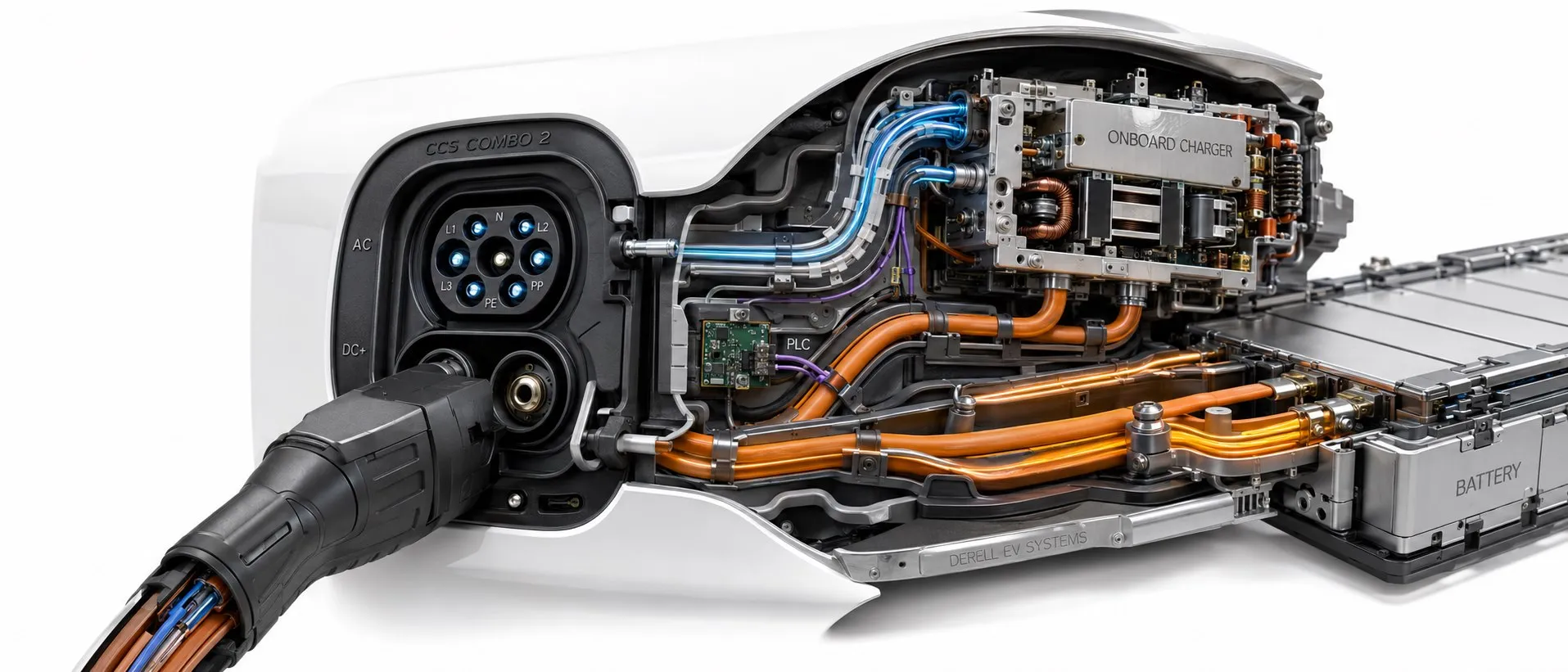
Understanding AC and DC charging through a shared vehicle inlet
CCS stands for Combined Charging System. It brings AC and DC charging together around a shared vehicle inlet, addressing power connections, control signals and digital communication as a system. It is more than the name of a plastic plug or two large contacts. Within electric vehicles and charging systems, understanding CCS means distinguishing physical connector compatibility from the charging power a vehicle can actually accept.
CCS is based on international standards developed with contributions from multiple manufacturers. CharIN is an industry association involved in its adoption, implementation guidance and interoperability work. Describing CCS simply as a connector standard developed by CharIN alone is incomplete.
Editor's note: The vehicle inlet is shared; the cable connector used for AC and DC need not be the same. A suitable Combo 2 vehicle inlet accepts a Type 2 connector for AC charging and a CCS2 connector for DC charging. A vehicle with only a Type 2 inlet lacks the lower DC contacts and cannot directly accept a CCS2 fast-charging connector. This is central to the difference between Type 2 and CCS.
What is the difference between CCS1 and CCS2?
CCS1, also called Combo 1, combines a Type 1/SAE J1772-based upper interface with two additional DC power contacts. CCS2, or Combo 2, uses a Type 2-based design. Both provide lower DC+ and DC− connections for DC charging, but the upper geometry and mating arrangement differ.
CCS2 forms part of Europe's Type 2 and Combo 2 charging arrangements. North America also has the SAE J3400/NACS interface alongside CCS1. Check the vehicle's actual inlet rather than relying on descriptions such as “American vehicle” or “European vehicle.” CCS1 and CCS2 are not mechanically interchangeable, and adapter suitability cannot be established from the connector shape alone.
Where does the energy go during AC and DC charging?
During AC charging, power enters through the vehicle's appropriate AC contacts and is converted to DC by the on-board charger, or OBC. During DC fast charging, conversion takes place in the station's power electronics, and energy passes through the DC contacts into the vehicle's battery power circuit. The vehicle's battery management and protective systems continue to supervise the process. The difference between AC and DC vehicle charging therefore includes where conversion takes place.
The upper part of a CCS DC connector need not contain all the power contacts present in an AC connector; protective earth and control connections are used. A Combo 2 inlet accepting a Type 2 connector also does not establish support for three-phase or 22 kW AC charging. The practical differences between 7.4 kW, 11 kW and 22 kW charging depend on the OBC, phase configuration and available supply.
Is 350 kW the upper limit for every CCS product?
No. There is no single fixed current or power rating for all CCS equipment. Cables, connectors, vehicle inlets, cooling systems and stations can have different ratings. For example, a verified Phoenix Contact CCS2 cable assembly specifies 1000 V DC, 500 A continuous current and up to 700 A in Boost mode under appropriate conditions. These are ratings for a particular product, not universal ratings for CCS cables or vehicles.
On the DC side, power is approximately P = U x I. If the station and vehicle permit it, 400 V at 500 A gives approximately 200 kW, while 800 V at 500 A gives approximately 400 kW. Different voltages therefore produce different power levels at the same current limit. The relationship between voltage and wattage helps explain station ratings. An “800 V architecture” also does not mean that voltage remains exactly 800 V throughout a charging session.
Why is the station's advertised power not always available?
Actual charging power depends on the vehicle's acceptance limits, battery voltage, state of charge, temperature and the station's available output at that moment. Power generally decreases as the battery fills. A cold or excessively hot battery, shared power modules and cable thermal limits can also affect the result. The characteristics of the electric vehicle battery consequently matter as much as the connector.
For example, seeing 120 kW at a station advertised as 350 kW does not, by itself, identify a faulty connector. Consider the vehicle and station voltage-current ranges, the charging curve and any thermal limitation. Peak power and average session power are different; charging-time calculations should not assume that peak power is maintained throughout the session.
What do the standards and communication protocols do?
The IEC 62196 series addresses physical and electrical requirements for charging connections; IEC 62196-3 covers dimensional compatibility for DC and combined AC/DC vehicle couplers. The IEC 61851 series concerns the operating and safety framework for conductive charging systems. The relevant edition matters for design and procurement: the 17 October 2026 check confirmed IEC 62196-3:2026 with its August 2026 corrigendum incorporated.
For CCS DC charging, the vehicle and station use high-level communication based on DIN SPEC 70121 or the ISO 15118 series, depending on the implementation. This uses PLC, meaning Power Line Communication, over the control pilot line. The parties coordinate the session and power limits; inserting the connector does not initiate uncontrolled power transfer.
Does every CCS vehicle support Plug & Charge and V2G?
Plug & Charge facilitates automatic authorization using the vehicle's digital identity and contract information in supported ISO 15118 implementations. The vehicle, station and service infrastructure must provide the necessary support. A CCS inlet alone does not mean a card or app will be unnecessary at every station. CCS sessions using external identification methods also exist.
V2G means transferring energy from a vehicle to the grid. ISO 15118-20 defines communication messages and sequences for bidirectional power transfer, but operation also requires suitable vehicle hardware, bidirectional charging equipment and the relevant operating infrastructure. Communication support alone does not prove that bidirectional power electronics are installed.
Safety involves more than the connector
Locking, protective earthing, control signals and, depending on the product, temperature measurement form part of safe charging. Functions such as insulation monitoring, residual-current detection and power-contactor control are assessed within the vehicle and station design. They should not all be described as devices built into every connector housing.
High-current systems may use liquid cooling and contact-temperature monitoring. Distinguish continuous-current ratings from temporary Boost ratings, and account for ambient temperature and cooling conditions. Do not use a damaged, overheated connector or one with deteriorated contacts. End the session using the equipment's specified procedure; do not force a locked connection apart.
What should be checked when selecting a cable or inlet?
First identify whether the product is CCS1 or CCS2 and whether it is a cable-mounted connector or a vehicle inlet. Then assess operating voltage, continuous and temporary current, cable length, conductor cross-section, cooling requirements, temperature sensors, locking arrangements and environmental conditions together. Check how the product's protection rating is specified in its mated and unmated states.
An adapter does not add missing DC charging hardware to a vehicle or automatically make an unsupported protocol compatible. Follow the connection arrangements permitted by the vehicle manufacturer. For everyday use, charging an electric vehicle at home is often assessed as a separate AC solution; solar-powered vehicle charging also requires attention to energy management and installation capacity alongside connector type.
Related charging topics and interfaces
Explore electric vehicle charging standards for the wider framework, CHAdeMO and GB/T to compare other DC interfaces, the electric vehicle charging FAQ for practical questions and the IEC 62196 series for connection standards. Different interfaces serving the same purpose should not be treated as directly interchangeable products.
Links to installation protection and cabling
Useful background includes grounding, residual-current protective devices and DC fuses. On the power circuit, assess cable current-carrying capacity by cross-section together with voltage drop. These fundamentals do not replace product-specific instructions and the system calculations required for a charging installation.
Continue exploring vehicle technology
For further explanations of batteries, motors and vehicle operation, visit the electric vehicle frequently asked questions.
Sources
CharIN: CCS architecture and basic technical distinctions
CharIN: CCS Basic implementation guide, connections and communication
IEC 62196-3:2026: scope and August 2026 corrigendum
ISO 15118-20: communication scope for bidirectional power transfer
Phoenix Contact: CCS2 continuous current, Boost and cooling example
Tesla: state-of-charge and temperature effects on charging power
U.S. Joint Office of Energy and Transportation: CCS1 and SAE J3400 interfaces