
Teco A510 ac drive
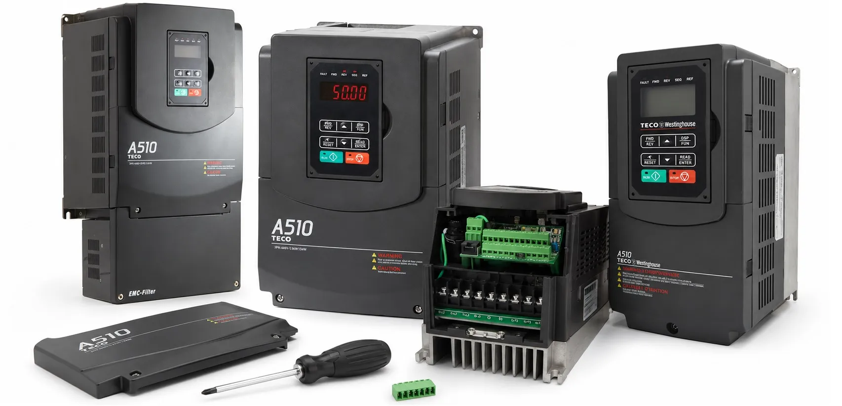
TECO A510 AC Drive – High Performance Inverter
TECO A510 is a high-performance AC motor drive designed for demanding industrial machinery, crane, lifting and motion applications. Its advanced motor control functions allow a wide range of machine control requirements to be handled with a single inverter platform.
The A510 series supports several motor control methods including V/F, vector control, speed, torque and position control. Depending on the motor and application configuration, the drive can also be used in applications requiring advanced motion and servo motor control.
Technical references for this series:
→ TECO A510 fault codes
→ TECO A510 user manual
External RUN Button Connection
The control terminals include 24VG and 24V connections for digital input operation. The input logic can be configured according to the required NPN or PNP switching method.
For NPN operation, a connection can be made from the 24VG terminal through an external switch or push button and then to the S1 digital input terminal.
To operate the drive from an external RUN command, set parameter 00-02 to 0001. The inverter will then receive its RUN command from the external terminal instead of the keypad.
External Potentiometer Connection
The A510 terminal block provides GND, AI1 and +12V terminals for an external potentiometer. Connect the potentiometer wiper to AI1, with the remaining terminals connected to GND and +12V.
To use the external potentiometer as the frequency command source, set parameter 00-05 to 0001. Frequency can then be adjusted from the connected external potentiometer.
TECO A510 Quick Start Parameters
00-02 – RUN Command Source
0000: RUN command from the keypad
0001: External RUN command
0002: RUN command via RS485 communication
0003: Operation through the PLC function
00-05 – Frequency Command Source
0000: Frequency setting from the keypad
0001: Frequency command from an external potentiometer
00-12: Maximum frequency / upper frequency limit
00-13: Minimum frequency / lower frequency limit
00-14: Acceleration time
00-15: Deceleration time
02-01: Motor rated current (A)
02-03: Motor rated speed (rpm)
02-04: Motor rated voltage (V)
02-05: Motor rated power (kW)
02-06: Motor rated frequency (Hz)
After the power and motor connections have been completed, enter the appropriate motor nameplate values before starting the drive. Motor current, voltage, power, frequency and rated speed should match the connected motor.
Factory reset: Set 13-08 = 6
TECO A510 Features
• Integrated V/F and V/F + PG, SLV, SV, PMSV and PMSLV control modes
• 32-bit MCU and ASIC based control architecture
• Dual-core processor
• Speed, torque and position control functions
• Advanced vector control technology
• Static and rotary Auto Tuning
• Built-in communication through the RJ45 interface
• Built-in EMC filter
• IEC / EN 61800-3 compatibility
• Normal-duty and heavy-duty operating ratings
• PLC and PID functions as standard
• Parameter lock function to prevent unauthorized changes
• Safe Torque Off (STO) support
• Fire Mode support
Additional functions include automatic restart after momentary power loss, speed detection, overload detection, eight preset speed values, PLC functions, acceleration and deceleration control, S-curve operation, PID control, torque boost, slip compensation, frequency limits and automatic energy saving.
The TECO A510 control parameters are organized into 23 main parameter groups. General drive settings are mainly located in the 00-** group, while motor information and advanced motor settings are found primarily in the 02-** group.
TECO A510 Parameter Groups
00 – General settings
01 – V/F control settings
02 – IM motor data and motor parameters
03 – External terminal digital input and output functions
04 – External terminal analog input and output functions
05 – Frequency setting parameters
06 – Automatic operation parameters
07 – Start / Stop command parameters
08 – Protection functions
09 – Communication parameters
10 – PID function parameters
11 – Performance control parameters
12 – Display parameters
13 – User parameter group
14 – PLC settings
15 – PLC display parameters
16 – LMC function parameters
17 – Auto Tuning parameters
18 – Slip compensation parameters
19 – Wobble frequency parameters
20 – Speed control parameters
21 – Torque control and position control parameters
22 – IPM motor information and motor parameters
TECO A510 Technical Documents
→ TECO A510 Fault Codes – Alarm, trip and inverter fault information
→ TECO A510 User Manual – Installation, wiring, parameter and operating information
→ TECO inverter price list
→ TECO Automation