
Single phase vs three phase VFD
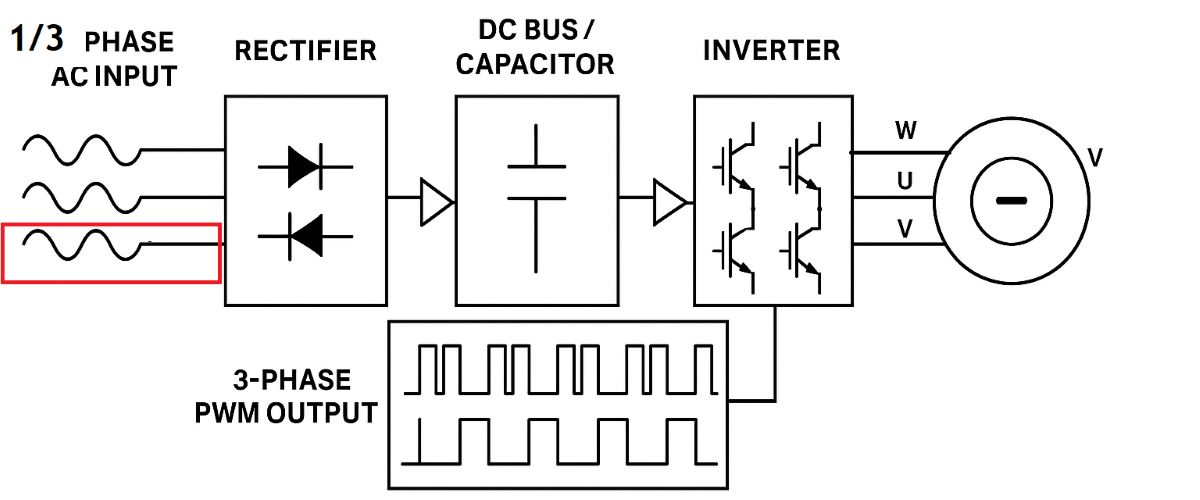
Single-phase input versus three-phase input VFD: what is the difference?
A single-phase input, three-phase output VFD takes power from an approved single-phase supply and delivers a controlled three-phase output to a compatible three-phase motor. A three-phase input, three-phase output VFD takes power from a three-phase supply and also delivers controlled three-phase motor output. The first choice depends on the available supply; the motor still needs the right output voltage and current. The Schneider Electric ATV12 example explicitly specifies 230 V single-phase input and 230 V three-phase output for one model, while another model in that series is not rated for single-phase input.
At a glance: choose a manufacturer-rated 1φ→3φ drive where only suitable single-phase power is available; choose a 3φ→3φ drive for an appropriate three-phase supply. In either case, match its output voltage class, continuous current and overload rating to the motor and machine. The number of input phases does not tell you the output voltage by itself: three-phase input drives exist in different voltage classes.
On this page: the practical difference · rectifier, DC bus and PWM · original animation · 230/400 V motor example · drive selection · frequently asked questions · related guides and drives.
How do the two supply arrangements compare?
1φ input → 3φ motor output: a dedicated drive can operate a suitable three-phase motor where an appropriate single-phase utility feed is available. A typical 230 V-class example accepts about 200–240 V single-phase and produces a variable-frequency three-phase output of the corresponding voltage class. Because power enters on fewer supply conductors, input current and the stress on the input rectifier and DC-link components matter when sizing the installation. Consult the exact drive nameplate and installation manual for permissible supply and motor ratings.
3φ input → 3φ motor output: the drive accepts a specified three-phase input and controls a three-phase motor. It can be a 230 V class product or a 400 V class product, among other ratings. Access to three-phase power does not mean every 3φ-input drive produces 400 V, and a 230 V single-phase feed does not become 400 V motor power merely because the output has three phases. See Schneider Electric’s explanation of standard drive output-voltage limits.
The two drive types can offer similar speed-control features such as V/f control, vector control, acceleration ramps and motor protection. Choose those functions according to the application. Supply phase alone does not guarantee more torque, better precision or a fixed percentage of energy savings.
How does either VFD create three-phase output?
First, AC becomes DC: an input rectifier takes the incoming single-phase or three-phase supply and feeds the DC bus. Capacitors and, on some models, inductors smooth that bus. Next, DC becomes controlled three-phase power: the inverter switches its output devices using pulse-width modulation (PWM) so the motor sees three controlled fundamental voltage components. Output frequency sets the rotating-field speed, subject to the motor’s pole count and load-dependent slip. See the AC drive operating path for an overview.
The DC-bus waveform changes with the input: with a conventional single-phase full-wave rectifier, the main rectified ripple repeats at twice the line frequency; a conventional six-pulse three-phase rectifier produces six charging pulses per line cycle. On a 50 Hz feed that suggests 100 Hz versus 300 Hz ripple repetition in these simplified cases. Actual voltage ripple amplitude depends on the load, capacitor bank, source and rectifier design. Schneider Electric notes the higher DC-bus ripple and input bridge stress when eligible drives are operated from a single-phase feed.
Try the original VFD animation
Press Start, switch between 1φ→3φ and 3φ→3φ, then move the output-frequency slider. Follow the input, DC bus and three motor-output phases; choose fan/pump or conveyor to see how the illustration describes different load demands. Both input selections end at a three-phase motor output. Stop freezes the illustration. The displayed speed, slip, torque and current are teaching estimates, not measured values, closed-loop feedback or a product specification.
Reading the animation: a four-pole motor has a synchronous speed of 1,500 rpm at 50 Hz and 900 rpm at 30 Hz. Its loaded shaft speed is generally slightly lower because of slip. Neither the illustrated DC-bus ripple nor the animated motor speed is a substitute for checking the actual drive and motor datasheets.
Can a 230 V single-phase VFD run a 230/400 V motor?
Often yes, if the motor nameplate explicitly permits 230 V delta (Δ), the 230 V-class drive supplies suitable three-phase output and its rated output current covers the motor’s 230 V delta nameplate current. A motor marked 230/400 V Δ/Y normally connects in delta at 230 V three-phase or star (Y) at 400 V three-phase. This describes the voltage between the VFD’s motor output phases. Check the actual motor connection diagram before moving any links on its terminal board. Schneider Electric’s motor-connection guide gives the winding-voltage reasoning.
A 400 V-only motor, or one whose nameplate does not permit 230 V operation, is a different case. A standard 230 V-class single-phase-input VFD does not automatically produce rated 400 V three-phase output. Use a manufacturer-approved solution with the required output voltage, or select an appropriately rated motor; do not expect a voltage setting alone to restore the unavailable motor voltage. Conversely, a 230/400 V Δ/Y motor paired with a suitable 400 V-class, three-phase-input drive normally uses its 400 V star rating and matching nameplate current.
How should you select the drive?
1. Identify the supply: record actual line voltage, phase count, frequency, available branch-circuit capacity and installation conditions. Select a VFD whose input label explicitly supports that supply. When only single-phase power is available, the simplest starting point is a drive designed and rated for single-phase input. A drive labelled only for three-phase input must not be moved to single phase on the strength of a rule of thumb: manufacturer approval, model-specific derating and specified protective devices are required. Schneider Electric lists approved models and differing restrictions.
2. Match the motor: check its voltage, Δ/Y connection, rated motor current, power, frequency and operating speed. Size the drive to deliver the required continuous motor current and overload duty; kW alone can hide a current mismatch. For the motor-side connection, use the drive’s three output phases, typically U/V/W, as described in its manual; the U/V/W guide explains the phase labels. A standard three-phase-output VFD is intended to drive a suitable three-phase motor, not a conventional single-phase capacitor motor.
3. Identify the load: a centrifugal fan or pump often has a variable-torque characteristic; a loaded conveyor commonly needs significant torque through a wide speed range. Positive-displacement pumps and some other pumps can also behave as constant-torque loads. Select the overload class and acceleration time for the actual starting load. A heavy-duty drive may be appropriate where starts are demanding.
For a loaded conveyor, torque boost may help at low speed on some drives; motor identification and the control mode matter too. Neither feature changes the drive’s rated continuous output current.
4. Complete the installation design: follow the manufacturer’s specified input wiring, fuse or breaker selection, earthing, cable lengths, enclosure temperature and ventilation requirements. Input line reactors and input filters address supply-side conditions; a motor-side output reactor addresses different cable and motor issues. Danfoss’s harmonics guide explains how rectifier topology and mitigation affect the supply. Harmonics are not exclusive to bargain-priced drives, and CE marking is not a numerical guarantee of zero harmonics.
5. Commission against the actual motor: enter its nameplate voltage, rated current, frequency and speed or pole count, then select the correct control mode, minimum and maximum frequency and protections. Check loaded starts, steady current and temperature. The basic VFD settings and motor overload protection guides give further context.
Frequently asked questions
Does a single-phase-input drive make my motor single phase? No. Its incoming supply can be single phase while its motor output remains three phase. The two sides have different ratings and terminal labels; see the single-phase supply explanation.
Can I use a 3φ-input VFD on 1φ supply by connecting only two input terminals? Only when the manufacturer expressly permits that exact model, with any required derating and installation provisions. Another three-phase-input model can trip on input phase loss or overheat; see the phase-loss guide and Schneider Electric’s approved-model guidance.
Does three-phase input always mean more motor power? No. Available power depends on the supply capacity, the particular drive’s output current and overload rating, and the motor. Three-phase distribution often supports a broader range of industrial drive sizes, but compare specific models.
Will changing to a VFD save 30% energy? There is no universal saving percentage. On centrifugal fans and pumps, reducing speed can substantially lower demand compared with throttling, but savings depend on the operating point, hours, piping or duct losses and duty cycle. Danfoss distinguishes theoretical affinity-law estimates from real installations. Input-phase choice alone does not determine savings.
Can the drive power a complete three-phase machine with contactors and heaters? A normal VFD motor output is intended for the rated motor under its specified application; it is not a general three-phase utility outlet for an entire machine. Schneider Electric expressly separates the two uses.
Choose by supply: single-phase input, three-phase output VFDs · three-phase input VFDs · all AC drives · VFD technical library.
Understand the power path: single-phase AC · DC bus · PWM · motor output U/V/W · input filters · output reactors.
Motor control and commissioning: V/f control · vector control · constant-torque loads · acceleration and deceleration · basic parameters · phase-loss diagnosis.
Manufacturer documentation: Schneider Electric on 1φ input and 3φ output · output-voltage limit · single-phase approval and derating · motor delta/star connection · Danfoss load curves · input harmonics. Product ratings and wiring details always come from the exact model manual and motor nameplate.