
Yaskawa J7 fault codes
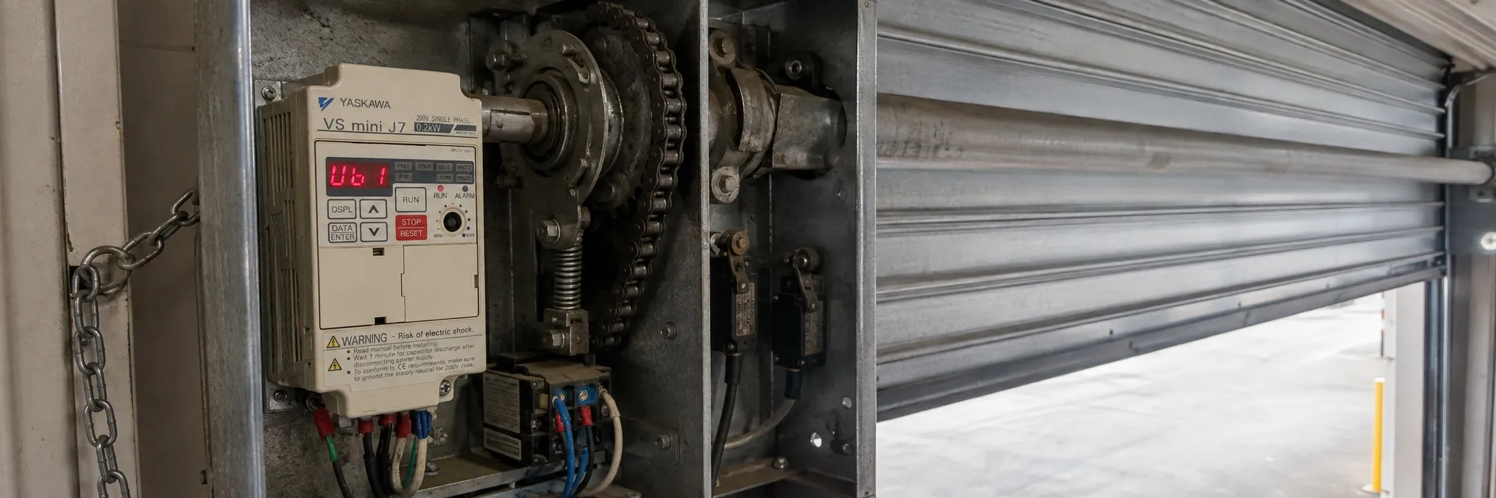
Yaskawa J7 VFD fault diagnosis and corrective actions:
Fault Diagnosis and Corrective Actions:
This section explains the display of alarms and faults, the explanation of fault conditions, and the corrective actions to be taken in the event of a failure of the VS mini J7.
Corrective actions for models without a digital operator:
+ Perform input fault reset or turn the power supply OFF and ON.
+ If a fault is not corrected:
+ Turn the power supply OFF and check the wiring and control logic.
UV (Main circuit low voltage):
The main circuit DC voltage drops below the low voltage detection level while the inverter output is OFF.
+ 200V: Main circuit DC voltage drops below approximately 200V (160V for single phase).
+ 400V: Main circuit DC voltage drops below approximately 400V.
Items to check:
- Power supply voltage
- Main circuit power supply wiring is connected.
- Terminal screws are tightly fastened.
OV (Main circuit overvoltage):
The main circuit DC voltage exceeds the overvoltage detection level while the inverter output is OFF.
+ Detection level: Approximately 410V or more (about 820V for 400V class).
Items to check:
- Power supply voltage
OH (Cooling fin overheating):
Input air temperature increases while the inverter output is OFF.
Items to check:
- Input air temperature
CAL (MEMOBUS communication standby):
Correct data has not been received from the PLC when power is ON and parameters n02 (operation command selection) are 2 or n03 (frequency reference selection) are 6.
Items to check:
- Communication devices and transmission signals
OP! (Parameter setting error when setting parameters via MEMOBUS communications)
OP1: Two or more values are set for multifunction input selection. (parameters n36 - n39)
OP2: The relationship between V/f parameters is not correct. (parameters n09, n11, n12, n14)
OP3: The setting value of the motor nominal current exceeds 120% of the inverter nominal current. (parameter n32)
OP4: The upper/lower limit of the frequency reference is reversed. (parameters n30, n31)
OP5: The setting values of skip frequencies 1 and 2 are not appropriate. (parameters n49 - n50)
OP9: Carrier frequency setting is incorrect. (parameter n46) Check the setting values.
OL 3 (Over torque detection): Motor current exceeded the value preset in parameter n98. Reduce the load and extend the acceleration/deceleration time.
SER (Sequence error): The inverter is receiving local/remote selection commands from the multifunction terminal or change signals of the communication/control circuit terminal while outputting. Check the external circuit (sequence).