
Yaskawa 616 G5 fault codes
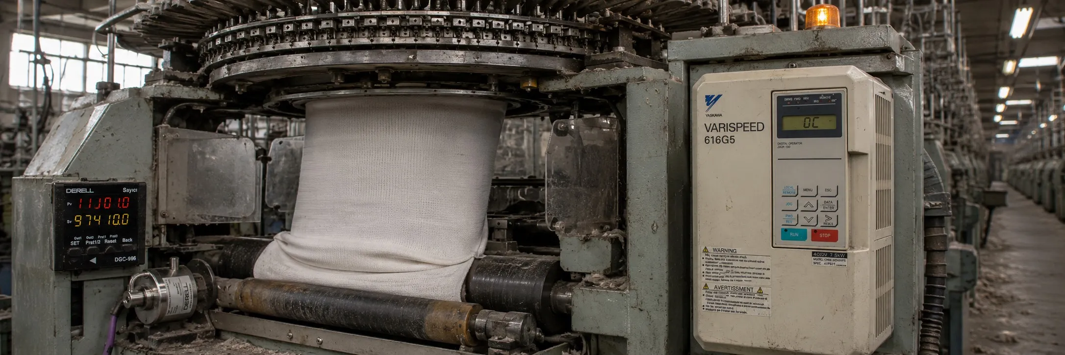
MOTOR FAULTS AND CORRECTIVE ACTIONS
(1) If any of the following faults related to the motor occur, check the cause and apply the relevant corrective action.
(2) If these checks and corrective actions do not solve the problem, immediately contact your YASKAWA representative.
Table 32 Motor Faults and Corrective Actions
Fault Check Point Corrective Action
Motor not rotating Power supply voltage, power supply terminals L1, L2, L3 applied. CHARGE LED is ON
Turn ON the power supply
Turn OFF the power supply and then turn it ON again
Check the power supply voltage
Ensure terminal screws are tight
Use a rectifier-type voltmeter to test for correct voltage output at output terminals U(T1), V(T2), W(T3) Turn OFF the power supply, then turn it ON again
Motor locked due to overload* Reduce the load and unlock
Fault displayed on operator screen* Check the troubleshooting table
FORWARD or REVERSE operation command entered* Check the wiring
Frequency adjustment voltage entered* Correct the wiring
Check the frequency adjustment voltage
Reference selection (b1-01), operation method selection (b1-02) correct* Enter the correct setting value
Motor rotation direction reversed
Wiring of terminals U(T1), V(T2), W(T3) correct* Match the wiring to the motor's phase sequence U(T1), V(T2), W(T3)
FORWARD and REVERSE wiring operation signals entered* Correct the wiring
Motor rotating, but variable speed not available
Wiring of frequency adjustment circuit correct* Correct the wiring
Reference selection (b1-01), operation method selection (b1-02) correct* Check the reference selection or operation method selection with the digital operator
Load too large* Reduce the load
Motor rpm too high or too low
Motor ratings (number of poles, voltage) correct* Check the motor nameplate specifications
Acceleration/deceleration speed change ratio for gears, etc. correct* Check the speed changer (gears, etc.)
Maximum frequency setting value correct* Check the maximum frequency setting value
Voltage between motor terminals not excessively reduced* Check the V/f characteristic values
Motor rpm not stable during operation
Load too large* Reduce the load
Load change too large* Reduce the load change
Increase inverter motor capacity
Using 3-phase or single-phase power supply* For 3-phase power supply, phase open* Check the wiring if the power supply phase is open for 3-phase power supply
For single-phase power supply, connect an AC reactor to the power supply
UV1
DC Bus Low Voltage
Main circuit low voltage (PUV) Low voltage in the direct current main circuit during operation
Detection level
400 V class Approximately 380 V or less
UV2
Control Circuit Low Voltage
Control circuit low voltage (CUV) Low voltage in the control circuit during operation
UV3
MC Response
MC failure Front charge contactor opened during operation
Check the power supply wiring
Correct the line voltage
UV
Low Voltage -
Momentary power loss
Main circuit direct current voltage dropped below the PUV level
Control power supply dropped below the CUV level
Front charge contactor opened
OC Overcurrent
Inverter output current exceeded the OC level
Check the motor coil resistance
Extend the acceleration/deceleration time
Check the motor insulation
Multimeter check
GF Ground Fault
Inverter output grounding current
exceeded 50% of the inverter's nominal current
Ensure that the motor insulation is not damaged
Ensure that the connection between the inverter and motor is not damaged
OV DC Bus Overvoltage
Overvoltage (OV) Main circuit direct current voltage exceeded the OV level
Detection level
400 V class Approximately 800 V
Extend the deceleration time, add a braking circuit
SC Short Circuit
Load short circuit (SC) Inverter output (load) short-circuited
Check the motor coil resistance
Check the motor insulation
PUF DC BUS Fuse Open
Fuse blown (FU)
Direct current circuit fuse blown
Output transistors damaged
Check the damaged transistor, load side short circuit, grounding, etc.
OH1 Cooler MAX Temperature
Cooler overheating (OH1)
Transistor cooler temperature exceeded the allowable value
Check the fan and ambient temperature
Ol1 Motor Overloaded
Inverter output exceeded the motor overload level
Reduce the load
OL2 Inverter overload
Inverter output exceeded the inverter overload level
Reduce the load, extend the acceleration time
OL3 Over Torque Detection 1
When torque detection selection 1 is enabled (L6-01=1 to 4), inverter output current (in V/f control) or inverter torque reference (in vector control) exceeded torque detection level 1 (L6-02)
OL4 Over Torque Detection 2
When torque detection selection 2 is enabled (L6-01=1 to 4), inverter output current (in V/f control) or inverter torque reference (in vector control) exceeded torque detection level 2 (L6-05)
PF Input Phase Loss
Input open phase
There is an open phase in the inverter input power supply
Check the line voltage
Tighten the input terminal screws
LF Output Phase Loss
Output open phase
There is an open phase in the inverter output
Check the output wiring
Check the motor impedance
Tighten the output terminal screws