
What types of sensors can be used with DC drives?
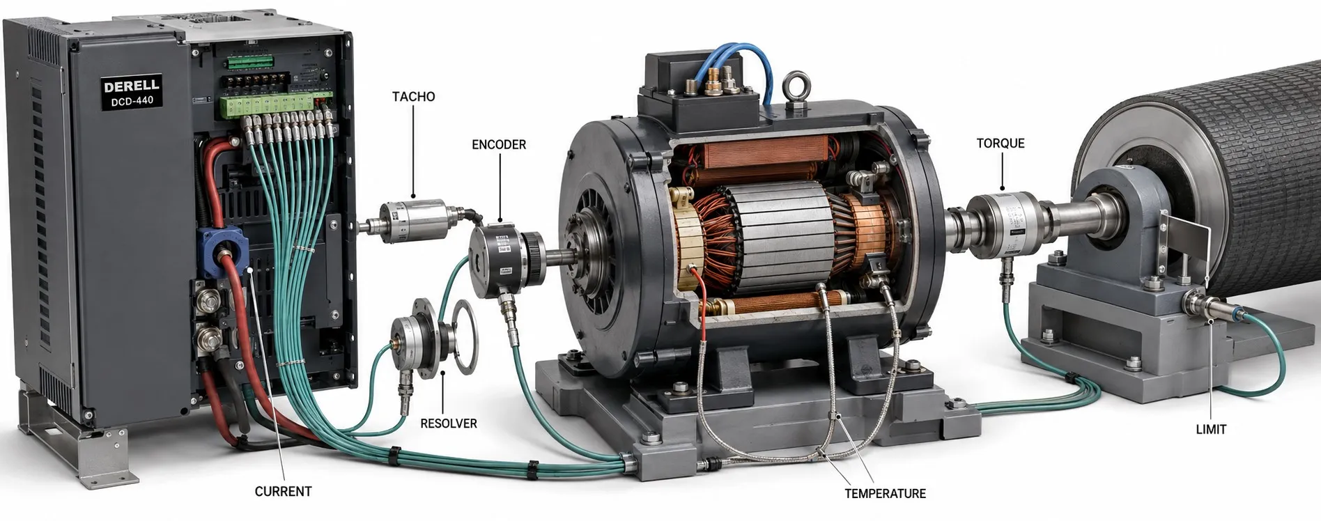
Which sensors can be used with DC drives?
DC drive systems can use encoders, tachogenerators, current and voltage transducers, temperature sensors, position sensors and process instrumentation. Compatibility depends on the task and the electrical interface. A sensor that is useful on the machine is not necessarily suitable for direct connection to the drive.
Start by asking what the measurement must achieve. In a DC drive system, an encoder may close the motor speed loop, a temperature sensor may support motor protection, and a vibration sensor may report to a maintenance system. Motor feedback, equipment monitoring and process measurement have different timing and interface requirements.
Speed measurement: tachogenerators and incremental encoders
A tachogenerator produces an electrical signal as its shaft rotates. With a DC tachogenerator, voltage magnitude represents speed and polarity indicates direction. It requires a compatible tacho input with the correct voltage range and calibration. A handheld tachometer or a panel speed display does not automatically provide a usable drive-feedback output.
An incremental encoder generates pulses from shaft movement. Quadrature A/B channels provide information for speed and direction, while an optional Z channel supplies a once-per-revolution reference. Appropriate speed feedback allows the drive to respond when mechanical loading changes.
Resolution is only one selection criterion. Check supply voltage, TTL or HTL signal levels, output circuitry, maximum input frequency and cable requirements. A differential line-driver interface is not wired or received in the same way as a single-ended output.
Pulse-rate example: An encoder producing 1,024 cycles per revolution on one channel generates 1,024 × 1,500 / 60 = 25,600 Hz at 1,500 rpm. Four-edge quadrature decoding can produce 102,400 counts per second. Check how the manufacturer defines PPR or CPR and whether the input limit refers to channel frequency or decoded counts.
Absolute encoders and resolvers: when position matters
An absolute encoder reports a coded position within its specified measuring range. Its interface must be supported by the drive, motion controller or option module. An SSI encoder, for example, cannot simply be connected to an ordinary A/B pulse input.
A resolver requires excitation and provides sine/cosine information related to shaft angle. A dedicated interface or resolver-to-digital converter processes those signals. Resolver support is not universal, and using a resolver does not by itself guarantee high positioning accuracy. Mechanical installation, conversion electronics and control design also matter.
Receiving position data does not automatically give a speed drive a position-control function. The required control architecture must include a position loop where the application needs one.
Current measurement: choose a technology that can measure DC
Armature current is important for torque regulation, and separately excited motors may also require field-current monitoring. Suitable Hall-effect current transducers can measure DC while providing galvanic isolation. Other approaches include shunts with suitable measurement electronics and fluxgate-based transducers.
A conventional electromagnetic current transformer cannot directly measure steady DC. Some thyristor converters measure AC-side currents and process them according to the converter arrangement to obtain armature-current information. That does not make an ordinary CT suitable for measuring DC simply by placing it around a motor conductor. The difference between current-sensing technologies is fundamental to selection.
Many drives already contain the measurement circuitry needed for their current loop. Connecting an external current sensor to a general analog input does not make it the drive's internal current-feedback device. That function must be explicitly supported. An external transducer may instead provide independent monitoring or information for a process controller.
Voltage measurement: keep power and signal circuits distinct
Armature, field or supply voltage can be monitored using built-in circuitry or a suitable external voltage transducer. Depending on the converter, this information may support monitoring, protection or speed estimation.
A 0–10 V control input must not be connected directly to the motor's power voltage. An external measurement interface must have the correct input range, isolation, transient capability and output format. Understanding the power and control sections of the drive helps avoid treating these circuits as interchangeable.
Temperature: distinguish thermal protection from measurement
Motor-protection PTC thermistors show a pronounced resistance increase around their response temperature. They are useful for overtemperature detection, but that application does not necessarily provide a continuous, accurate temperature reading. A compatible thermistor input or protection relay is required.
Pt100 and Pt1000 RTDs can support numerical temperature measurement through suitable RTD inputs or transmitters. NTC devices, thermocouples and thermal switches can also be used with matching interfaces. Insulation between a winding-mounted sensor and the accessible control circuit must be adequate for the installation.
Infrared instruments measure surface temperature. Emissivity, viewing angle and measurement spot size influence the reading, and motor-frame temperature does not directly identify the hottest winding point. Account for this limitation when using infrared data for maintenance and condition monitoring.
Torque and web tension: measure the mechanical quantity you need
A suitable torque transducer measures shaft torque. Some designs use strain gauges to detect mechanical deformation. A strain gauge is not a voltmeter, and the drive's current-based torque estimate is not the same measurement as an independent shaft transducer.
Load cells can measure force through an appropriate mechanical arrangement. In winding and unwinding systems, they may provide the feedback for a tension loop. A raw mV/V bridge output generally requires excitation and a measuring amplifier; it is not a direct substitute for a standard 0–10 V signal.
Position, presence, pressure and vibration
A mechanically linked potentiometer can act as a position transducer. A speed-setting knob, however, normally provides a command. Turning a potentiometer to request a speed does not measure the motor's actual speed.
Inductive, photoelectric and capacitive sensors can detect products, reference positions or material presence. A proximity sensor counting gear teeth can also support speed measurement, provided its switching frequency and the low-speed update interval suit the application.
A pressure sensor measures the process served by a DC-driven pump or hydraulic system. Vibration sensors can support motor, bearing or machine condition monitoring. These measurements may go to the drive, a PLC or a separate monitoring platform; they do not all belong in the fast motor-control loops.
Direct connection or a PLC interface?
A drive's dedicated encoder or tacho input is intended for supported speed-feedback devices. Process measurements may instead use compatible analog or digital inputs, signal converters or PLC communication. Ethernet is a networking technology, not a sensing principle. A networked sensor still measures a specific physical quantity.
Check whether the interface expects 0–10 V, ±10 V, 4–20 mA, PNP/NPN switching, pulses or a particular digital protocol. Sampling, filtering and communication delays must suit the required control response. Follow the relevant equipment instructions for cable screening, grounding and separation from power wiring.