
What is frequency reference input for vfd?
What is a VFD frequency reference input?
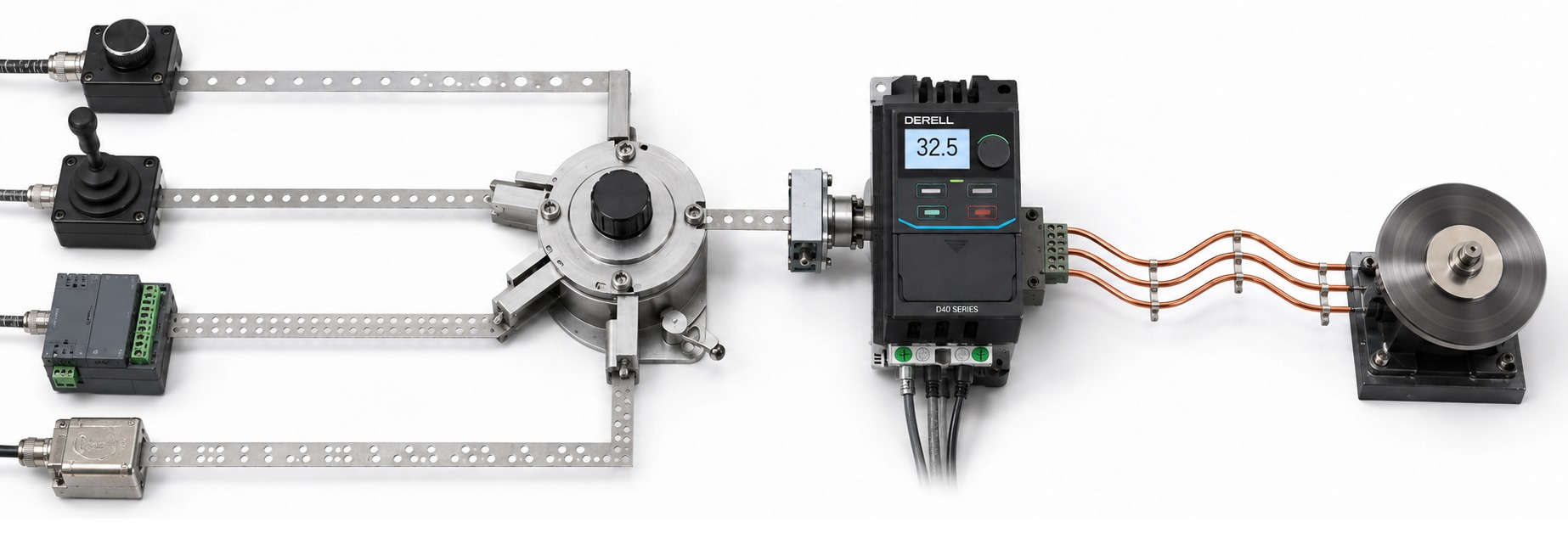
A frequency reference is the speed command that tells a variable frequency drive what output-frequency target the machine requires. It can come from the drive keypad, a potentiometer, an analog signal, a PLC, the drive's internal PID controller or an industrial communications network.
The key word here is reference. It is the requested value, not necessarily the actual motor speed. Acceleration and deceleration ramps, frequency limits, current limiting and induction-motor slip can all create a difference between the requested reference and the motor's instantaneous shaft speed.
Typical external reference signals include 0–10 V and 4–20 mA, but modern drives may also accept preset digital speeds, pulse references or commands sent over Modbus, CANopen, Profibus or industrial Ethernet.
Explore the OtomasyonAVM knowledge base: Potentiometers · Digital Potentiometers · Analog Control · Sensors · PID with a VFD · PLC & HMI
Where can a frequency reference come from?
Drive keypad: The operator enters a value such as 35.00 Hz directly from the VFD panel. This is useful for commissioning, testing and stand-alone machines.
Potentiometer: A conventional industrial potentiometer can operate as a voltage divider using the drive's reference supply, analog common and voltage input.
Electronic potentiometer: A panel-mounted digital/electronic potentiometer can provide a repeatable 0–10 V or 4–20 mA command while giving the operator a numerical display and push-button adjustment.
PLC analog output: A PLC analog-output module can generate 0–10 V or 4–20 mA and send the speed reference directly to the VFD.
Industrial communications: Instead of converting the command into an analog signal, a controller can write the frequency reference numerically over RS-485/Modbus, CANopen, Profibus or an Ethernet-based network.
Internal PID: The drive's PID controller can calculate the required frequency automatically from pressure, flow, level or another process variable.
JOG or fixed-frequency modes: Some commands temporarily override the normal analog reference. JOG frequency is a common example.
How do 0–10 V and 4–20 mA references work?
The small demonstration below uses a simple example mapping: 0 V or 4 mA = 0 Hz, while 10 V or 20 mA = 50 Hz. A real drive does not have to use this exact mapping; minimum frequency, maximum frequency, bias and gain can normally be configured.
Motor rpm is approximate. Actual shaft speed depends on slip, mechanical load and the selected motor-control method.
What is a 0–10 V frequency reference?
0–10 V is one of the most common analog speed commands used with VFDs. If a drive is configured so that 0 V represents 0 Hz and 10 V represents 50 Hz, a 5 V command corresponds to approximately 25 Hz.
That relationship is not universal. The drive may be configured so that 0–10 V represents 10–60 Hz, 20–50 Hz or another range. Many drives provide separate parameters for gain, bias, lower frequency and upper frequency.
For manual speed adjustment, a conventional industrial potentiometer can be connected as a voltage divider using the VFD's reference supply, analog common and voltage input. Always check the permitted resistance and wiring diagram for the actual drive.
What is a 4–20 mA frequency reference?
4–20 mA is an industrial current-loop signal. Four milliamps normally represents the bottom of the configured range and 20 mA represents the top. With a 4–20 mA → 0–50 Hz mapping, 12 mA sits at approximately the middle of the command range.
The use of 4 mA as a live zero is valuable because a valid zero command is different from complete loss of loop current. Where the VFD supports suitable diagnostics, an abnormally low current can therefore help identify a broken wire or transmitter problem.
Current loops are also widely used for longer cable runs and field instrumentation, which makes 4–20 mA particularly common when the frequency command comes from a remote transmitter, PLC analog output or industrial controller.
0–10 V or 4–20 mA?
0–10 V is simple and very convenient for local panel wiring, conventional potentiometers and short analog-control runs.
4–20 mA is often preferred for longer distances and electrically difficult industrial environments. The VFD input must, however, be configured for a current signal. Many drives use a parameter, jumper or DIP switch to select voltage or current mode; others provide separate AVI and ACI terminals.
The wiring diagram for the actual VFD should therefore be checked before applying the signal.
Using a potentiometer as the speed reference
A conventional potentiometer acts as a variable voltage divider. The wiper produces a voltage proportional to knob position, and the VFD reads that voltage as its analog reference.
Where a numerical display, push-button adjustment or 4–20 mA output is required, an electronic potentiometer may be more suitable.
These devices generate a low-power control signal. They should not be confused with adjustable power supplies.
Frequency reference and RUN command are different
The frequency reference tells the drive how fast the motor should run. The RUN command tells it whether it should run at all.
A potentiometer may be requesting 35 Hz while the motor remains stopped because the RUN command is inactive. Conversely, a RUN command can be present while the active reference is zero.
RUN/STOP commands may come from the keypad, hardwired terminals or communications. The classic push-button arrangement is explained in our 3-Wire VFD Control guide.
How can a PLC send a frequency reference?
A PLC can send the speed command through an analog output module, typically as 0–10 V or 4–20 mA, or it can write the reference numerically through an industrial network.
With communications, the same link can normally carry much more than a speed command. Depending on the VFD, the PLC may also read actual output frequency, motor current, DC-bus voltage, drive status and fault information.
This makes the frequency reference part of the wider industrial communication architecture rather than a single analog wire.
Can a sensor directly control VFD frequency?
Yes, but there are two very different control structures.
An analog sensor can be mapped directly to the frequency reference. For example, a 4–20 mA process signal could be scaled so that an increasing measurement produces an increasing VFD frequency.
In a true closed-loop process application, however, the sensor is usually feedback, not the final frequency command. The drive's PID controller compares that feedback with a setpoint and calculates the required frequency reference.
For example, a pressure transmitter does not normally tell a booster pump, “Run at 37 Hz.” It tells the controller what the actual pressure is; the PID algorithm decides what motor frequency is required to maintain the target pressure.
Editor's note: When an analog speed-control problem appears in the field, I start with the command chain, not by blaming the drive. What voltage or current is actually reaching the terminal? Is analog common correct? Is the VFD input configured for voltage or current? Does 10 V actually appear as 100% reference on the drive display? Until those questions are answered, replacing the VFD is guesswork.
Does 0 V always mean 0 Hz and 10 V always mean 50 Hz?
No. Analog-reference scaling is configurable on most industrial drives. The lower and upper signal points can be assigned to different frequencies, and the drive may provide bias, gain, minimum-frequency and maximum-frequency parameters.
A machine could therefore use 0–10 V to command only 20–50 Hz. Turning the potentiometer fully down would then reduce the drive to 20 Hz rather than zero.
Some applications can also use inverse scaling, where increasing analog signal reduces the requested frequency. The available options depend on the VFD.
Why does frequency reference not equal actual shaft speed?
A four-pole induction motor has a synchronous speed of 1500 rpm at 50 Hz, but its actual rotor speed under load is slightly lower because of slip.
Where actual shaft speed must be known accurately, an encoder can provide real feedback. High-performance vector-control systems can use that feedback to regulate actual speed much more tightly.
This is the distinction between commanding a frequency and actually measuring what the motor shaft is doing.
Why does analog-reference wiring matter?
VFD motor cables carry high-frequency PWM switching and can be a significant source of electromagnetic interference. Sensitive 0–10 V and 4–20 mA control wiring should therefore be routed, shielded and grounded according to the manufacturer's EMC recommendations.
A small error on a 0–10 V reference can become a noticeable speed variation on a tightly scaled application. If the requested frequency appears to wander, measure the reference signal itself before assuming that the motor or VFD is faulty.
Commissioning checks
First confirm the active frequency-command source: keypad, analog input, communications, PID or another configured mode.
Then verify the analog-input type, correct terminal, analog common, voltage/current selection, lower and upper scaling, frequency limits and input filtering.
Finally test the system with known values. For example, apply 0 V, 5 V and 10 V or 4 mA, 12 mA and 20 mA and check whether the active frequency reference shown by the VFD follows the expected scaling.
In short: the frequency reference tells a VFD how fast the process wants the motor to run. The command can come from a potentiometer, digital potentiometer, PLC analog output, sensor, PID controller or an industrial communication network. Once the source and scaling are configured correctly, the frequency reference becomes one of the main links between the drive and the wider automation system.