What is PWM?
Hello there,
From our work on examining technical terms;
Pulse-width modulation (PWM) is a modulation process or technique used in most communication systems to encode the amplitude of one signal into a direct pulse width or duration for transmission of another signal, usually a carrier signal. Although PWM is also used in communication, its main purpose is to control the power supplied to various electrical devices, especially inertial loads such as AC/DC motors.
- PWM concept briefly; It is the basic name of the trigger systems used to control almost everything with a square wave. With its simple definition, PWM is what the flip flop circuit we made with the 555 IC in high school is.
The square wave signal thus produced will be a sequence of pulses and these pulses will be in the form of a square wave. That is, the square wave generated at any given time will either be high or low. To expand a bit, let's consider a 12V square wave signal, in which case the wave signal would be 12V (high) or 0V (low) at zero level. The time that the signals stay high is called “on time”, the time that the signal stays low is called “off time”.
For a PWM signal, we need to look at two important parameters associated with it,
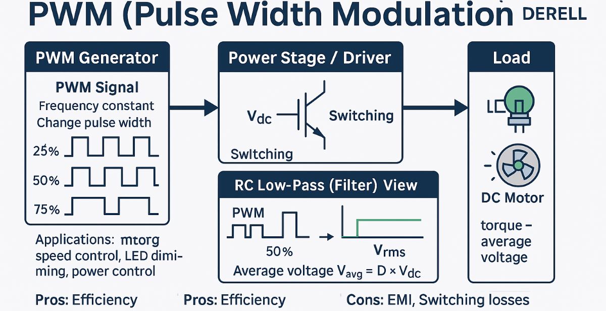
1- PWM duty cycle
2- PWM frequency.
Why is the PWM Control system needed?
We made a simple analogy above. In the form of a typical square wave control method. However, don't let this definition mislead you, PWM control is not that simple control format.
Controlling with analog signals is a very difficult and more unstable method. Carrying signals is very troublesome and open to outside interference. For example, if you have a 7vdc signal, it may be lost for many reasons, such as the distance between the target and the source, interference or environmental, for example, heat. The signal you send as 7v may reach the receiver as 5.5v. So essentially analog control cannot be in a fully controllable signal position.
PWM signal, on the other hand, unlike analog, references the frequency of the signal, not the voltage. (As we wrote above, PWM consists not only of frequency but also of amplitude.) Therefore, even if the square signal from the source reaches the receiver with small voltage differences, the receiver can read it and evaluate it.
Dear friends, in order to understand PWM technology and to know why it created a new control format, it is necessary to know the concepts of MOSFET and IGBT. Transistors may be insufficient for PWM control. However, the fast cutting capabilities of high frequency IGBT modules or Mosfets, which are popular lately, are essential for control with PWM signals.
One of the biggest advantages of PWM is very little power loss. Regulating power levels, mainly by limiting electric current and using an analog device or potentiometer to control power output, is similar to, for example, accelerating/decelerating a car with a brake device. Thus, it means wasted signal energy causing power loss as heat. PWM, on the other hand, actually turns it off (or pulls it to zero) instead of limiting the power output.
What is the equivalent of PWM control systems in industrial control system?
Pulse Width Modulation (PWM) is a high-end current control technique that lets you control the speed of motors, the heat output of heaters, and much more in an energy-efficient (and often quieter) way. We can say that PWM is used in all inverter controlled products.
PWM changes the speed of the devices' motors so they only consume as much power as they need, but you don't see the usual result of burning unused current as heat. An example of an old alternative is a simple transistor circuit that changes the current through it by changing its resistance.
How to calculate PWM frequency?
The frequency of a PWM signal determines how fast a PWM completes a period. A Period is the full ON and OFF time of the PWM signal. Frequency calculation formulas are given below.
Frequency = 1 / Time Period
Time Period = On time + Off time
PWM technique is the main backbone in ac iverter driver and servo systems (which interests us). And it is used as a PWM carrier, and higher PWM switching frequencies are increased every day to create a waveform close to the sinusoidal curve. The lower the PWM frequency, the more noisy the motor will run. The higher the PWM frequency, the lower the frequency buzzing sound you will hear from the motor. Frequency noise is zero in drives that can give full sine output (which is not available in our country).
The higher the switching frequency an ac drive system can reach and operate at that point, the better. As a result of our own tests, we observed that as we increase the PWM frequency, the basalization rate of the devices increases. (The most successful brand in this test was TOSHIBA+Siemens mm440).
The purpose of this page is not for our customers who have more detailed information, but for those who have technical knowledge at the beginner level.
Your shopping cart is empty!