
How is voltage distributed in an electrical circuit?
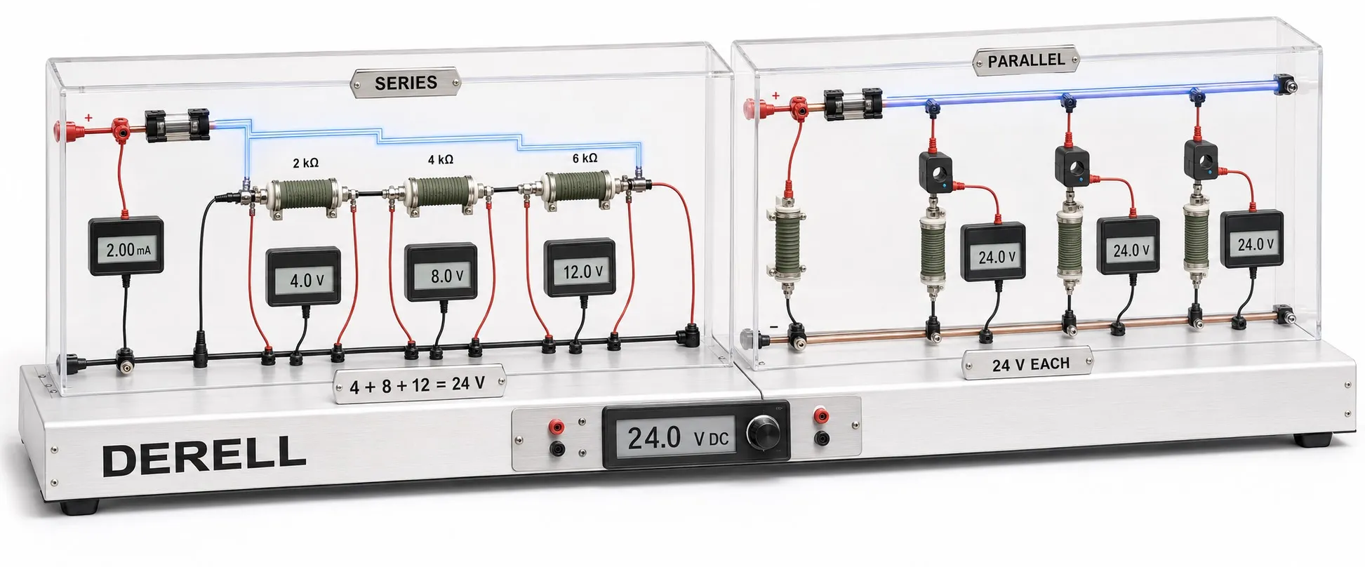
Voltage distribution in a circuit depends on how components are connected and on their electrical characteristics. Series resistors carry the same current, with voltage divided in proportion to resistance. Branches connected across the same two nodes have the same voltage, although their currents may differ. For background, see what voltage means and voltage versus current.
How does voltage divide in a series circuit?
When no current branches off at their junction, series resistors carry the same current. This means their currents are equal to each other, not necessarily constant over time. Using Ohm’s law, the voltage across each resistor is U = I × R.
Connect R1 = 3 Ω and R2 = 6 Ω in series across an ideal 9 V DC supply. Their total resistance is 9 Ω. Neglecting wire and source resistance gives a current of 1 A, a 3 V drop across R1 and a 6 V drop across R2: 3 V + 6 V = 9 V.
I = U / (R1 + R2)
U1 = U × R1 / (R1 + R2)
U2 = U × R2 / (R1 + R2)
These expressions apply to a resistive divider with no additional load drawing current from its junction.
Animation: dividing 9 V across two resistors
The arrow marks the location being explained. It does not represent travelling voltage or electron speed. The displayed values describe steady state; they do not develop one after another.
Check resistor power ratings: R1 dissipates 3 W and R2 dissipates 6 W in this example. Ordinary 0.25 W resistors are unsuitable. Using 3 kΩ and 6 kΩ keeps the same division ratio with an ideal current of 1 mA; the drops remain 3 V and 6 V. The relationship between voltage and power matters when selecting real components.
0 V is a reference; voltage does not flow into earth
Here, the supply negative terminal is our 0 V reference. Relative to it, nodes A, B and C are at 9 V, 6 V and 0 V. The voltage across R1 is 9 − 6 = 3 V; across R2 it is 6 − 0 = 6 V.
The circuit does not require this reference to be connected to physical earth. Saying that all the voltage has been “used up in the ground” is misleading. Electrical energy becomes heat in the resistors, while voltage describes a difference between points. Current returns to the source through the closed circuit.
Does voltage divide between parallel branches?
Connect both resistors directly across the same ideal 9 V source and each receives 9 V. The 3 Ω branch draws 3 A; the 6 Ω branch draws 1.5 A. Total source current is 4.5 A. These are ideal-source calculations; actual source current limits and resistor power ratings must also be checked.
Equal voltage in parallel means branches sharing the same two nodes have equal voltages at the same instant. It does not mean their voltage cannot change with time. In real installations, cable resistance may create differences at remote loads; see cable voltage drop.
What changes when a voltage divider is loaded?
A load connected between B and C is in parallel with R2. The lower leg therefore becomes R2 ∥ Rload. Adding a 6 Ω load across the original 6 Ω R2 makes this leg equivalent to 3 Ω. The output then falls from 6 V to 4.5 V.
A resistor divider alone is therefore not a substitute for a voltage regulator when supplying a device with changing current demand. Measurement and signal-scaling circuits must also account for the loading imposed by the connected input.
How are mixed and AC circuits analysed?
Kirchhoff’s voltage law states that the signed sum of voltages around a closed loop is zero in the lumped-circuit model. Kirchhoff’s current law relates currents entering and leaving a node. Series-parallel resistor networks can often be reduced to equivalent resistances before calculating node voltages and branch currents.
AC circuits containing capacitors or inductors require impedance and phase, not just resistance. Adding the RMS magnitudes of out-of-phase voltages arithmetically may give the wrong result. The 3 V + 6 V example here describes an ideal resistive DC circuit.
Which two points are being measured?
Voltage is measured in parallel between two points. Measuring B–C gives 6 V, A–B gives 3 V and A–C gives 9 V. Reversing the probes in a DC measurement changes the sign. Keep the voltage across a component distinct from a node voltage relative to a reference.
If a reading differs from the calculation, check the source voltage, resistor values, connections and attached load. Undervoltage or voltage fluctuations can also affect the result. A meter’s input resistance itself becomes a load, especially in high-resistance dividers.
Internal references and related guides
Fundamentals:
What is voltage? · Voltage versus current · What is resistance? · Ohm’s law
Measurement and calculation:
Measuring voltage · Voltage and wattage · Calculating voltage drop
Supply and troubleshooting:
Undervoltage · Voltage fluctuations · Voltage regulators
Further technical verification: divider loading
Texas Instruments — SSZTAW1, voltage scaling and load impedance