
what is treverse function?
What is the Traverse Function in a VFD?
For a Variable Frequency Drive (VFD), the "traverse function" refers to a special operating mode in which the output frequency of the VFD is fluctuated around a set frequency. This function is typically used in industries such as textile and chemical fiber processing, where precise control of the output frequency is required for the production process.
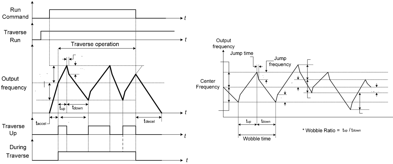
In the traverse function, the output frequency of the VFD is varied in a controlled manner around a set frequency, typically by fluctuating the frequency up and down within a certain range. This allows the operator to fine-tune the output frequency and achieve the desired results in the production process.
It is important to note that the specific details of the traverse function, including the range of frequency fluctuation and the set frequency, will depend on the specific VFD and the requirements of the application. It is essential to properly configure and calibrate the traverse function to ensure reliable and accurate control of the VFD.
Practical meaning first: the traverse function deliberately makes the motor speed “wobble” around a set frequency (fset). You don’t hold one fixed rpm; you keep it moving within a band so material doesn’t pile up in one spot. That’s why winders, spooling, weaving and film lines use it—uniform lay, fewer bands and a cleaner product surface.
Three knobs define the behavior: the set frequency that gives your base line speed, the amplitude (A) that defines how wide you sweep, and the period (T) that defines how fast you move from top to bottom. A triangular traverse gives constant slope and very uniform travel; a sinusoidal traverse is gentler on torque. In practice, “sweep width” is about 2A around the center.
Respect the drive limits. Your amplitude must fit the allowed band: A ≤ min(fset−fmin, fmax−fset). If you run vector control, keep accel/decel consistent with the chosen T, or you’ll force current limit. A tiny dwell at the ends can avoid mechanical snap; if the machine is sensitive, add smoothing so the motor doesn’t “jerk” at direction changes of the frequency ramp.
Typical field issues and what they mean: visible banding or moiré on film/yarn means your T is lining up with spool geometry—change T or the waveform. Edge hunting means A is too small; chatter or audible buzz means A is too big or ramps are too steep. If you have a separate tension loop, don’t fight it—make the traverse slower than the tension loop’s bandwidth or they will chase each other.
Commissioning recipe I trust: pick fset for the required line speed; start small at about A ≈ ±2–3 Hz and T ≈ 2–4 s. Verify fmin/fmax clamps, then increase A until distribution looks even. Watch motor current and alarms; if spikes show up, lengthen T or soften ramps. Finally, tell the operator that the “wobble” is intentional—once set, document the final fset, A, T so no one “tunes it out” later.
Your shopping cart is empty!