
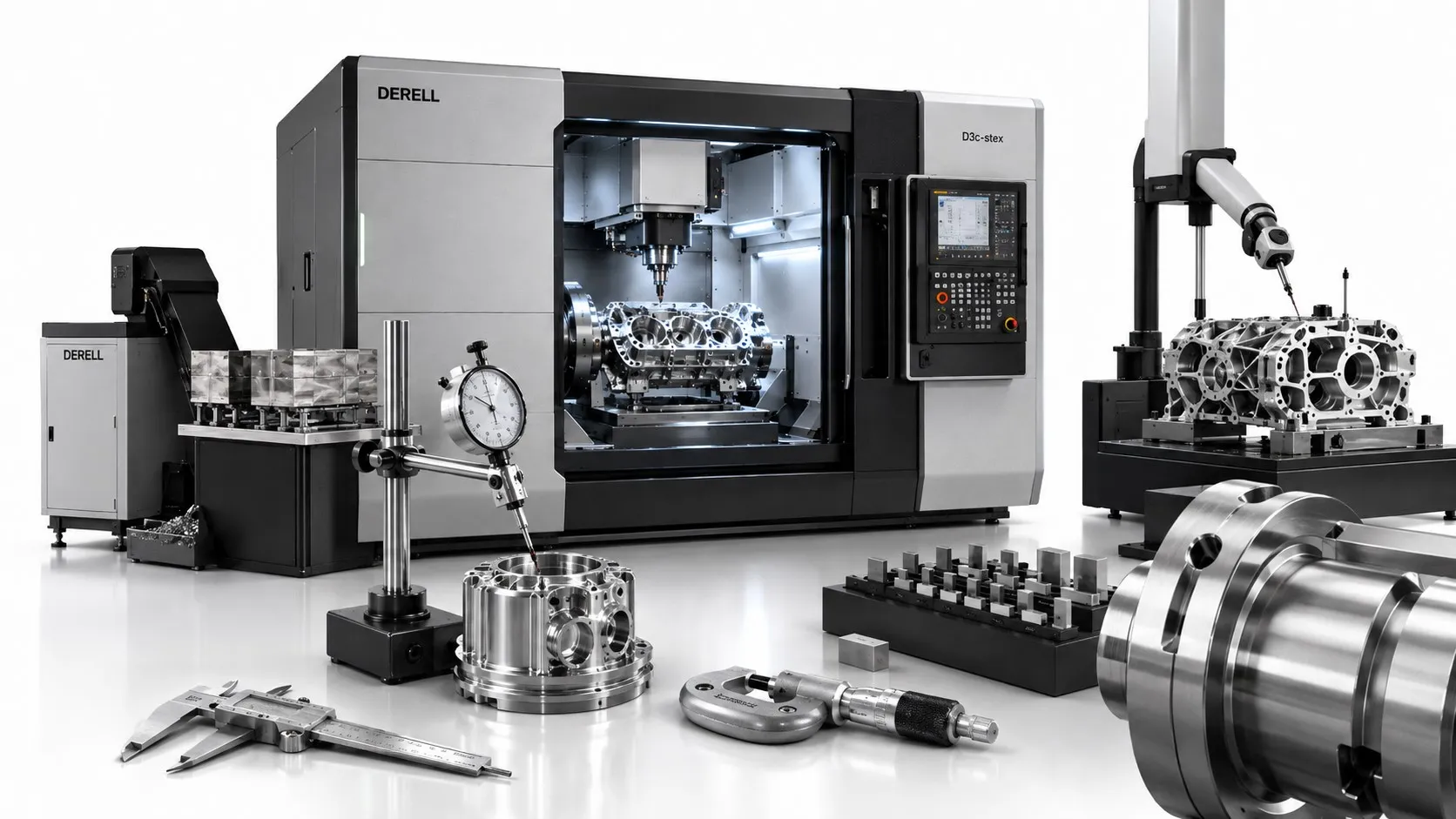
How precise are CNC machines?
A CNC machine does not have one universal precision figure. Its positioning performance is one part of the answer; the finished component also depends on tooling, workholding, temperature and inspection. Understanding CNC machining and how a CNC machine works helps distinguish a machine specification from a demonstrated production result. The useful question is whether a particular process can repeatedly meet the drawing.
Begin with the part tolerance
A drawing dimension of 20.000 ±0.005 mm allows a size from 19.995 to 20.005 mm. The permitted deviation is 5 µm on either side, and the full tolerance interval is 10 µm. Tolerance defines the acceptable result; it does not describe the machine's resolution or promise a particular process capability.
One micrometre is 0.001 mm. In inch units, 0.001 inch equals 25.4 µm and 0.0001 inch equals 2.54 µm. A tenth of a thousandth of an inch is therefore not sub-micrometre. Requirements in aerospace, medical and mould-making applications come from the component's function and drawing, rather than the industry label alone.
Read machine specifications in context
Some precision machining centres have manufacturer-stated positioning and repeatability performance on the micrometre scale. Makino's F5 Pro 6, for example, is described in these terms. That statement concerns a particular machine model; it is not a tolerance guarantee for every feature cut on it.
Ask which axis and travel length were tested, how direction and temperature were handled, and what operating condition applied. ISO 230-2 provides methods for evaluating positioning accuracy and repeatability of numerically controlled linear and rotary axes through repeated measurements. An axis test and a finished-part inspection establish different things.
Separate accuracy, repeatability and resolution
Positioning accuracy concerns how closely an axis reaches the commanded position. Repeatability concerns how closely it returns to the same position under specified conditions. A system can repeatedly reach a point that is offset from the intended target.
Resolution concerns the small changes a control or measurement system can distinguish. A CNC controller displaying three decimal places in millimetres does not prove that the machine cuts parts within ±0.001 mm. More displayed digits do not establish a smaller machining error.
For an illustrative example, suppose three parts intended to measure 20.000 mm are measured as 20.010, 20.011 and 20.012 mm. The results occupy a narrow 2 µm interval, but all exceed the 20.005 mm upper limit from the earlier drawing. Closely grouped results can still miss the target. This small example explains the distinction; it is not a formal repeatability test.
Follow the position feedback path
Servo control uses feedback to help servo motors follow motion commands. A linear encoder can measure linear axis position, while an absolute encoder provides an absolute position code. Encoder resolution is a component characteristic, rather than the accuracy of the complete machine.
Backlash, bearing behaviour, coupling errors and axis geometry can influence the result. The location of the feedback measurement also matters, as does deflection between the measured point and the cutting edge. Position feedback needs to be considered together with the mechanical structure.
Account for the actual cut
The workpiece material, part shape and clamping force affect the dimension produced. A thin wall may deform while clamped and change size when released. The cutting tool can introduce further variation through wear, runout and overhang. The cutting edge's loaded position matters, as well as the commanded coordinates.
Spindle speed and feed affect force and heat. Tool engagement can vary while machining complex geometries. Check CAM toolpath tolerances and the offsets used in CNC programming too. An exact coordinate command cannot prevent every mechanical or thermal deviation.
Surface finish is a separate requirement from dimensional accuracy. An Ra value of 0.8 µm describes surface roughness; it does not mean that every dimension is within ±0.8 µm. Quality control needs to assess size, form, location and surface requirements according to the drawing.
Allow for thermal change
The standard reference temperature for dimensional properties is 20 °C. Differences between machine, tool and workpiece temperatures can affect the result. Temperature sensors help monitor the conditions. Warm-up procedures and compensation can reduce thermal effects without eliminating every source of error.
As a learning calculation, take a 100 mm length and assume an expansion coefficient of 11.5 × 10⁻⁶/°C. A 5 °C temperature increase gives ΔL = α × L × ΔT, or approximately 0.00575 mm, equivalent to 5.75 µm. The actual coefficient depends on the material and alloy.
Maintain the machine and verify the measurement
Machine maintenance should cover lubrication, bearings, guideways, screw drives and the feedback system. Calibration characterises existing deviations; adjustment or compensation is a separate action intended to reduce them. Software compensation cannot always correct mechanical wear.
During prototype machining, inspect the first component with equipment suited to the feature, such as a micrometer, indicator, gauge or coordinate measuring machine. Include instrument calibration and measurement uncertainty in the assessment. A result close to a tolerance limit needs more consideration than simply reading the last displayed digit.
Demonstrate consistency in production
For volume production, the first acceptable part is only a starting point. Track tool wear, warm-up behaviour and changes introduced by repeated setups. CNC automation can support inspection cycles, a PLC can coordinate auxiliary equipment, and industrial IoT systems can record process data. Collecting data does not automatically make a measurement accurate.
Use process optimisation to achieve the tolerance the component actually needs. Unnecessarily tight requirements can increase CNC production costs through additional machining, environmental control and inspection. Assess precision through repeated, verified results on the intended part, under defined production conditions.