
What is multimeter?
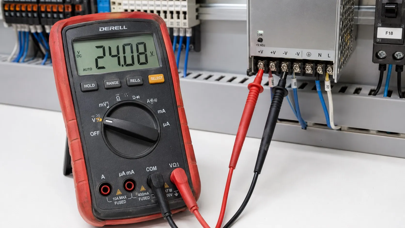
What is a multimeter and how is it used?
A multimeter is a multipurpose measuring instrument that measures electrical quantities such as voltage, current and resistance. It is used to check power supplies, trace connections and investigate electrical faults. A useful reading requires the correct measurement mode, input jack and circuit connection.
What does a multimeter measure?
Voltage measurement shows the potential difference between two points in volts (V). Current measurement shows current in amperes (A), milliamperes (mA) or microamperes (µA). Resistance measurement uses ohms (Ω), kilohms (kΩ) and megohms (MΩ). Ohm's law explains the relationship between these quantities for an ohmic element.
Depending on the model, a meter may also offer continuity testing, diode testing, capacitance measurement, frequency measurement, temperature measurement and data logging. These functions are not included in every multimeter; check the manual for current inputs, temperature accessories and measurement ranges.
Analog and digital multimeters
An analog multimeter displays its reading with a pointer and scale; a digital multimeter (DMM) uses a numerical display. Some digital models provide autoranging, HOLD and MIN/MAX. Autoranging selects a suitable measurement range; it does not necessarily select AC/DC or identify the correct input jack.
Resolution is the smallest displayed change; accuracy describes how close a reading can be to the actual value. For a 24.00 V reading with a 0.01 V least significant digit and an accuracy specification of ±(0.5% + 2 counts), the error limit is ±0.14 V. More digits alone do not guarantee greater accuracy.
Input jacks: COM, VΩ, mA and A
The black lead normally connects to COM. The red lead connects to VΩ for voltage, resistance and most auxiliary functions. Current measurement uses the appropriate mA/µA or A input within the meter's limits. COM does not mean protective earth; the measurement reference and grounding may serve different purposes.
After measuring current, return the red lead to VΩ. Leaving it in a current jack and placing the probes across a voltage source can create a short circuit. Turning the selector to voltage does not correct an incorrectly connected lead.
How to measure voltage
Select V⎓ for DC voltage or V~ for AC voltage, with the black lead in COM and the red lead in VΩ. Connect the probes in parallel across the two measurement points. With manual ranging, select a suitable range that covers the expected voltage.
24 V DC example: With the red probe on +24 V and the black probe on the 0 V terminal, a reading near 24 V is expected. Reversing the probes on a digital meter normally produces a negative reading. Choose the 0 V reference according to the equipment wiring diagram.
If the power supply reads 24 V while the load input reads 21 V, there is a 3 V difference. When both readings are taken under the same operating conditions, investigate voltage drop in the cables and connections. An unloaded reading may miss a problem; a weak connection can become apparent when the load operates.
How to measure current
For direct current measurement, connect the meter in series with the branch being tested; it then acts as an ammeter. Prepare the connection with power off, select the appropriate current input and AC/DC mode, then carry out the measurement under controlled conditions. Respect the input limit, fuse rating and maximum measurement duration.
Never connect a meter in current mode across a power supply. Higher currents may require a suitable clamp meter or current probe; a DC measurement requires an accessory that supports DC current. The voltage drop introduced by a series measurement can affect sensitive signal circuits.
Resistance and continuity testing
Measure resistance and continuity only on a de-energized circuit. Disconnect power, verify that voltage has been removed and safely discharge any capacitors. Select Ω for resistance. Parallel paths can alter an in-circuit reading, so isolate one terminal of the component when necessary.
Continuity mode quickly checks a conducting path through a cable, fuse or switch contact. The resistance threshold for the audible indication depends on the model. A beep does not prove that a connection will work properly under load; a weak connection may still conduct the meter's small test current.
In resistance mode, OL generally indicates an open path or resistance above the selected range; a reading near 0 Ω indicates a low-resistance path. Account for lead and contact resistance when measuring very small resistances. Interpret OL according to the selected function.
Checking diodes, LEDs and capacitors
In diode mode, the meter applies a test current and displays the forward voltage drop. Common silicon diodes may read approximately 0.5–0.8 V forward and OL in reverse. Results depend on diode type and test conditions. An LED may require more voltage than the meter can supply; failure to light is not sufficient evidence of a fault.
Before capacitance measurement, safely discharge the capacitor and check for residual voltage. A normal µF or nF reading does not fully establish acceptable leakage current or ESR. Similarly, a simple diode check of a transistor cannot reveal every fault that may occur in operation.
What does True RMS mean?
True RMS allows a meter to measure the effective value of nonsinusoidal AC waveforms within its stated limits. An average-responding meter calibrated for sine waves can give inaccurate readings on distorted waveforms. Check frequency bandwidth, crest factor and whether the function measures AC or AC+DC.
For PWM signals and drive outputs, the True RMS label alone is insufficient; follow the manufacturer's recommended measurement method and instrument requirements. An oscilloscope provides more information when investigating pulse shape, brief voltage dips or noise.
Multimeters in industrial automation
In PLC systems, a multimeter helps check the 24 V supply, input signals and common references. Evaluate NPN/PNP sensor outputs against the reference used by the input circuit. A displayed voltage alone does not prove that a sensor is wired correctly or can supply the required current.
Direct measurement of a 4–20 mA signal requires a series connection in the loop. If an existing 250 Ω measurement resistor is present, 1–5 V across it corresponds to 4–20 mA by Ohm's law. Adding a resistor without checking the loop can exceed the transmitter's permitted load.
CAT ratings and safe measurement
Assess measurement category and voltage rating together. The meter, leads and accessories must suit the measurement location. Do not use damaged leads; replace a current-input fuse only with the manufacturer's specified type. Live mains and panel measurements require appropriate training, equipment and working procedures.
Editor's note
Record where each reading was taken, the selected mode and whether the load was operating. Instead of “24 V present,” write “supply +/0 V: 24.1 V; sensor +/0 V: 21.8 V; load running.” This makes the next check more useful. A multimeter's value comes from interpreting the number in the context of the circuit.
Two common questions
Can a multimeter verify grounding quality? A standard resistance or continuity reading alone cannot establish the suitability of an earthing system; use the appropriate test instrument and method.
Will HOLD capture a brief fault? HOLD usually freezes the displayed reading. MIN/MAX capture also depends on the meter's response speed; very short events may require an oscilloscope.
Related topics
What is voltage? | What is current? | What is resistance? | Ohm's law | What is an oscilloscope? | What is an ammeter? | What is a PLC? | NPN / PNP sensors