
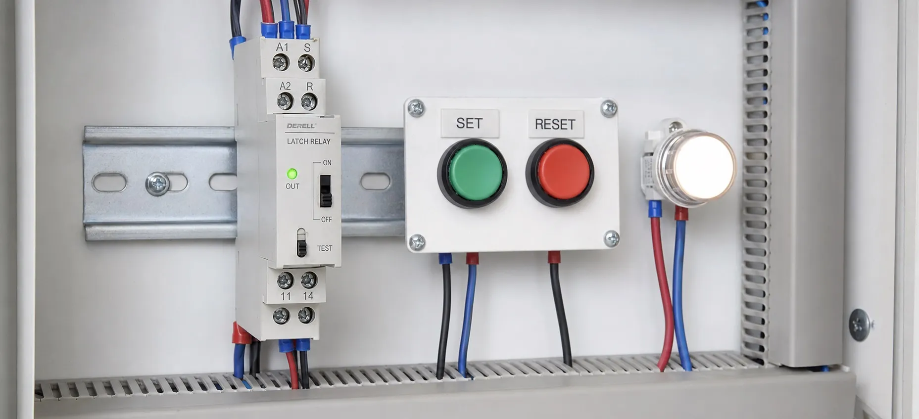
What is a latching relay?
A latching relay changes its contact position when it receives a suitable control pulse, then keeps that position after the pulse ends. Unlike a conventional electromechanical relay, it does not need continuous coil power to hold the selected state. You may also see it described as a bistable relay or keep relay.
Consider a battery-powered instrument that must keep one measurement path selected for several hours. Holding a conventional relay on would consume energy throughout that period. A latching relay can make the selection with a brief pulse and retain it through magnetic or mechanical holding. The instrument and the switched load still need their own power.
Set, reset and toggle: three different commands
Set selects one stable state; reset selects the other. With a suitable controller, a start pushbutton could request SET and a stop pushbutton could request RESET. Sending SET twice does not normally make a set/reset relay switch off again. Whether a button can drive the coil directly depends on the particular relay and circuit.
A toggle or impulse relay has a different command pattern: each input pulse alternates its state. Manufacturers may also call this a ratchet relay. A stepping relay is a broader category that can advance through several contact states. Check the operating diagram rather than assuming every product labelled “latching” will toggle on successive identical pulses.
The contact arrangement also matters. A changeover contact opens one path while closing another, so SET does not mean that every contact is closed. Interpret NO and NC markings using the reference state shown in the datasheet. An unpowered coil does not identify the contact position of a bistable relay.
How single-coil and dual-coil versions are driven
Many single-coil magnetic latching relays use DC pulses with opposite polarities. One polarity sets the relay and the reverse polarity resets it. A driver designed only to switch current in one direction may therefore be unsuitable.
A dual-coil relay provides separate set and reset windings. Terminal layouts, common connections and polarity requirements vary between models. Use the specified coil voltage and pulse duration, and do not energize both windings together unless the manufacturer explicitly permits it. There is no universal pulse length or terminal numbering scheme for all latching relays.
An electronic driver may use a transistor or a polarity-reversing bridge, depending on the relay. Coil suppression must match that arrangement. A conventional flyback diode placed directly across a reversing-polarity coil can short-circuit one command polarity. Suitable transient protection should be selected as part of the driver design.
Why a seal-in circuit is different
| Arrangement | Behaviour when coil power is removed |
|---|---|
| Conventional monostable relay | Normally returns to its rest position. |
| Bistable latching relay | Retains its set or reset position. |
| Conventional seal-in circuit using an auxiliary contact | The holding circuit drops out when its ordinary relay or contactor coil loses power. |
A seal-in circuit keeps supplying the coil after the operator releases the start button. A latching relay retains its contact state without that continuous supply. A latch instruction in a PLC or a memory function in a smart relay is different again: retention after a power interruption depends on the hardware and program settings. Relay contact memory is not the operating principle of microprocessor memory.
Contact ratings and coil ratings serve different purposes
The coil rating describes the control input; the contact rating describes the switched circuit. Coil current is not the same as load current. A relay marked “10 A” does not necessarily switch 10 A at every voltage or with every type of load.
An electric motor can draw substantial starting current, while an LED lighting driver may present a capacitive inrush. Both can stress contacts differently from a resistive load. Check the actual AC or DC switching rating, load category and electrical life. A suitable contactor may be needed for a demanding power circuit.
Continuous holding power is only one part of the energy calculation. For example, a conventional 0.5 W coil held on for 10 hours uses 5 Wh, or 0.005 kWh. Watts describe power and kilowatt-hours describe energy. A latching alternative uses energy during its control pulses, plus any driver consumption; the saving depends on how often it switches.
Retaining a command does not confirm a machine position
A retained contact can store a selection or a requested operating mode. It cannot by itself prove that a valve moved, a mechanism reached its destination or a load started. A panel indicator driven only from the stored command shows that command. Confirming physical position may require a suitable limit switch or other feedback device.
A power outage also deserves attention. Retaining a closed contact does not keep an unpowered load running, but that circuit may become energized when its supply returns. Specify the intended startup state and any required initialization. Transport shocks and installation conditions can also affect the initial state of some products, so an assumed factory position is not a substitute for checking the manufacturer's guidance.
Can an ordinary latching relay provide an emergency stop?
State retention alone does not make a relay a safety device. An emergency-stop function requires a suitable, assessed and validated control arrangement. The mechanical latching action of an emergency-stop pushbutton and the retained contacts of a general-purpose latching relay are separate functions.
The required safety function may use a suitable safety relay, safety PLC or another validated solution. Releasing or resetting an emergency-stop device must not automatically restart the machine. A general-purpose relay's ability to remember its previous state is therefore not enough to establish safe stopping or safe restart behaviour.
Checking a relay that does not set or reset reliably
A command pulse is evidence of a request, not proof that the contacts moved. Where needed, use appropriate feedback. A continuity test can check contacts after the circuit has been de-energized and isolated from other circuits. For intermittent operation, investigate pulse width, polarity and the voltage at the coil terminals; voltage drop in the supply or driver may prevent a reliable transition.