
what is IEC 61800?
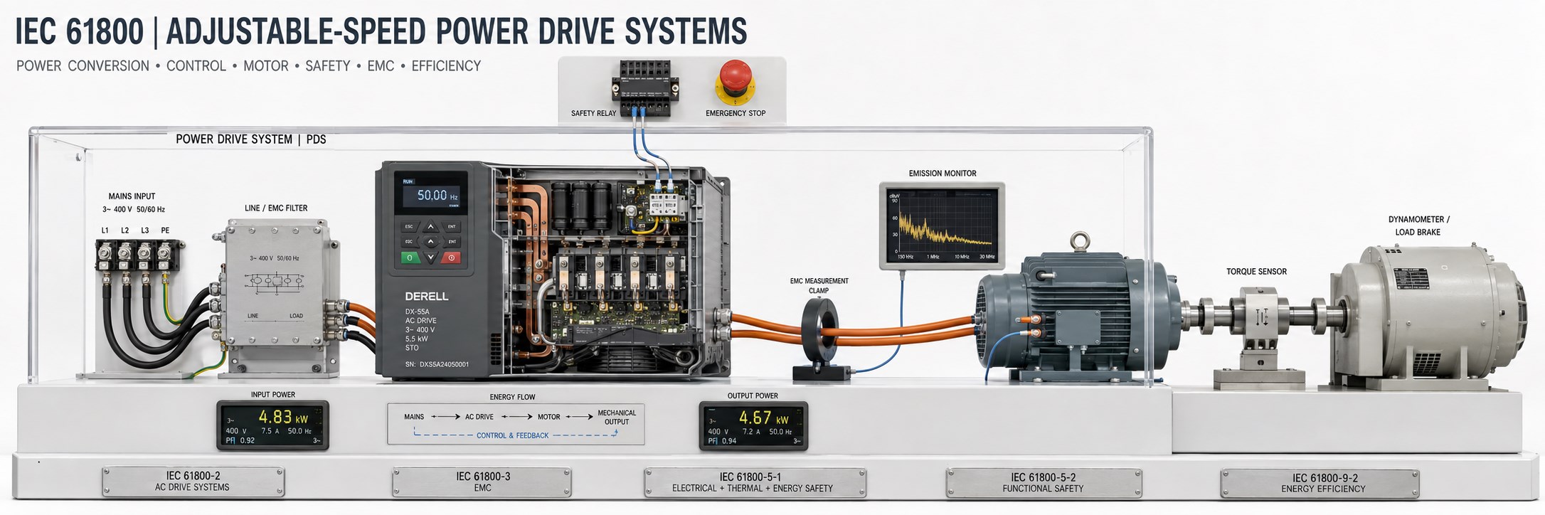
Matching each drive requirement to the right standard
IEC 61800 is an international series of standards for adjustable speed electrical power drive systems. Its separate parts address ratings, performance, electromagnetic compatibility, safety, communication interfaces and energy efficiency. It extends beyond setting an inverter’s speed. When selecting a variable frequency drive, a statement of “IEC 61800 compliance” should identify the specific part and edition being claimed.
The central abbreviation is PDS, meaning Power Drive System. Power conversion equipment, control and protection functions, and the motor are assessed together. BDM means basic drive module; CDM means complete drive module. The drive system including its motor has a different boundary from the pump, fan or mechanical load it drives. This distinction is particularly important when assessing efficiency.
Editor’s note: Part numbers do not divide drives into fixed kW bands. 61800-5-1 addresses electrical and thermal safety, while 61800-5-2 addresses functional safety. Meeting one part does not establish compliance with the other. EMC performance, safety functions and energy efficiency classes require separate assessment.
How should power and voltage limits be read?
A single limit of “0.75 kW–1000 MW and no more than 1000 V” is not a valid description of the entire series. Scope depends on the individual part, edition and system boundary. For example, IEC 61800-2:2021 covers AC motor drive systems supplied at input voltages up to 35 kV AC line-to-line at 50/60 Hz and/or 1.5 kV DC. These scope limits are not the product ratings of every inverter.
Ratings and performance: Parts 1 and 2
IEC 61800-1:2021 addresses general requirements and rating specifications for low-voltage DC motor drive systems. DC in this title refers to a system supplying a DC motor, rather than simply indicating a DC input connection. IEC 61800-2:2021 addresses the ratings, performance, operating conditions, testing and documentation of AC motor drive systems.
The former IEC 61800-4 addressed high-voltage AC drive systems; its requirements were incorporated into IEC 61800-2:2021. Describing Part 4 as a high-power traction standard is incorrect. IEC 61800-2:2021 also excludes traction applications and electric vehicles. Dividing the series into Parts 2-1, 2-2, 3-1 and 3-2 according to kW bands is not an accurate account of its structure.
Electromagnetic compatibility: Part 3
IEC 61800-3:2022 addresses electromagnetic compatibility (EMC). Both limiting the interference emitted by a drive and its immunity to external disturbances matter. Compliance depends on the intended environment, applicable category and installation conditions specified by the manufacturer. Filters, motor cables, shield connections and protective earthing therefore form part of the application assessment.
An integrated filter does not establish the same EMC performance at every cable length. Schneider Electric’s ATV320 guidance, for example, separately addresses cable shielding for EMC categories and output filtering for long motor cables. The practical lesson is to follow the installation instructions for the actual drive; a cable limit published for another model is not transferable.
Electrical safety and functional safety: Part 5
IEC 61800-5-1:2022 covers safety requirements concerning electrical, thermal and energy hazards, including fire and mechanical hazards. Insulation, protective arrangements and safe construction are assessed within this framework. IEC 61800-5-2:2016 addresses the functional safety of safety-related drive systems. The design and validation of product safety functions must be considered alongside the conditions for integration into machinery.
STO means safe torque off; SS1 means safe stop 1; SLS means safely-limited speed. STO prevents torque generation; it does not provide controlled braking or electrical isolation. Motion can continue because of inertia, and gravity can move a vertical axis. The application risk assessment must determine the necessary braking, load-holding and electrical isolation measures.
IEC 61800-5-3:2021 addresses functional, electrical and environmental requirements for safety-related encoders. An ordinary encoder should not automatically be treated as a safety component. Likewise, the presence of STO or a safety encoder does not establish that the complete machine achieves its required SIL or PL; the entire safety chain must be validated.
Communication, load duty and the motor interface
IEC 61800-7-1:2015 defines a generic interface between the drive system and the application control program. IEC 61800-7-201:2015 specifies profile type 1, while IEC 61800-7-301:2015 addresses the mapping of that profile, CiA 402, to network technologies. This family is not restricted to a single communication network. Ordinary drive communication does not automatically provide safety communication.
IEC TR 61800-6:2003 is a technical report providing guidance on load duty and corresponding current ratings. Distinguishing continuous loading from short-term overload helps avoid selecting a drive from motor kW alone. IEC TS 61800-8:2010 is a technical specification providing guidance on power interface voltage. These publications should retain their TR and TS designations when referenced.
Energy efficiency: Part 9
IEC 61800-9-1:2017 addresses the extended product approach, considering the energy performance of the driven equipment together with the motor and drive. IEC 61800-9-2:2023+AMD1:2025 addresses loss determination and energy efficiency classification. The IE class of a CDM and the IES class of a motor-and-drive PDS are different assessments. Neither should be confused with the motor’s own IE classification.
For a pump that spends much of its time at reduced speed, efficiency at the rated operating point alone is insufficient. Losses should be assessed against the speed, torque and operating-time profile. Danfoss’s efficiency calculation approach also distinguishes drive and motor-drive classes and considers load profiles. A high efficiency class does not guarantee identical energy savings in every application.
Applying the series to a real project
Consider a 400 V, 7.5 kW pump application. Establish the motor nameplate current, load characteristics, ambient temperature and required overload capability first. Then check drive ratings, EMC installation conditions, motor cabling and protective arrangements together. Where personnel access requires a safety function, determine the appropriate function and safety performance separately. Finally, assess energy losses using the actual operating profile. The 7.5 kW rating alone does not answer all these questions.
A specification should identify the standard part, edition, applicable amendments, product model and installation conditions. Match the drive’s declaration of conformity, safety manual and test documentation to those requirements. A drive’s compliance with IEC 61800 does not by itself establish compliance of the machine’s complete electrical equipment or safety functions.
Related topics
Within the same standards family: AC drive ratings, drive EMC, electrical and thermal safety, functional safety and IE and IES efficiency classes.
Supporting topics: EMC filters, earthing, drive selection, torque control and IEC 60204-1 electrical equipment of machines.
Edition note: Part titles and published editions were checked against official IEC catalogue records on 17 October 2026. Catalogue descriptions are not the full standards; use the applicable full text, corrigenda and amendments for project requirements.
Sources
IEC: IEC 61800-1:2021
IEC: IEC 61800-2:2021
IEC: IEC 61800-3:2022
IEC: IEC 61800-5-1:2022
IEC: IEC 61800-5-2:2016
IEC: IEC 61800-9-2:2023+AMD1:2025
ABB: Technical guide No. 10: Functional safety
Schneider Electric: ATV320 motor cable length and EMC installation
Danfoss: MyDrive Energy: efficiency classes and load profiles