
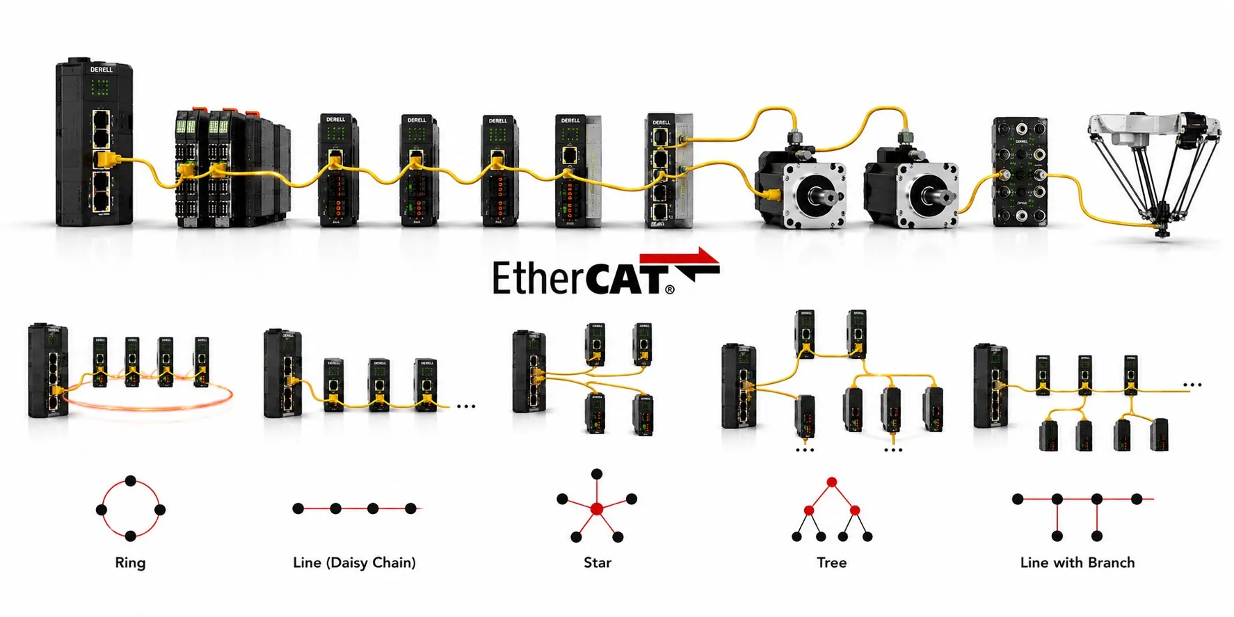
What is the topology of EtherCAT?
EtherCAT topology describes how the MainDevice, SubDevices and branches are physically arranged. EtherCAT is not restricted to one bus layout: line, tree, star, drop-line/branch structures and combinations of them are all possible. The important part is to separate the physical cable drawing from the logical path taken by an EtherCAT frame. Those two views are related, but they are not the same thing.[1]
How to read the image: it shows Ring, Line (Daisy Chain), Star, Tree and Line with Branch as physical layouts. A physical line already behaves as a logical ring because the EtherCAT frame returns from the last open port over the full-duplex path. A physically redundant ring is a different design and requires a return connection to a second MainDevice port.
A physical line already has logical ring behavior
The EtherCAT MainDevice sends a frame through the first SubDevice. Each SubDevice reads or writes its assigned data while the frame is passing. At the last open port, the frame is returned toward the MainDevice using the full-duplex Ethernet path. This is why a physically straight daisy chain can be described as a logical ring even though there is no separate cable from the last device back to the controller.[2]
This detail matters when learning how EtherCAT works. The return path of an ordinary line must not be confused with the additional cable used for redundancy.
Line / daisy chain follows the machine naturally
In a line, the MainDevice is followed by SubDevice 1, SubDevice 2, SubDevice 3 and so on. Drives, remote I/O and junction devices commonly provide an incoming and outgoing EtherCAT path, allowing the network to follow a conveyor, printing machine or sequence of servo axes without building the field segment around a normal Ethernet switch.[3]
The trade-off is the physical fault path. In a non-redundant line, a broken cable or failed intermediate path can make downstream devices unreachable. Good topology design therefore considers drag chains, replaceable modules and maintenance boundaries rather than only drawing the shortest cable route.
Branch / drop line creates local machine sections
A suitable EtherCAT SubDevice or EtherCAT junction can create a branch from the main path. One branch might serve a robot cell, another a measurement island, while the main line continues through the machine. ETG notes that branch/drop-line ports are integrated into many EtherCAT I/O products, reducing the need for separate active infrastructure.[4]
A normal office Ethernet switch is not the same thing as an EtherCAT junction in the cyclic field path. Use an EtherCAT branch/junction device that preserves the required port and logical-ring behavior. Beckhoff's EK1122 is a concrete example: it is a two-port EtherCAT junction intended for EtherCAT star structures and can also support Hot Connect.[5]
Star topology is possible—but it is not an ordinary switched-LAN star
An EtherCAT star uses an EtherCAT junction, multi-port EtherCAT device or suitable branch controller at the center. Each branch then participates in the EtherCAT traversal in a defined order. Physically it can resemble a conventional Ethernet star, but the field communication behavior is different.
This layout is useful when several machine zones radiate from one control cabinet: a sensor island, an encoder section and a servo section can each have their own cable path without turning the field network into a generic switched LAN.
Tree topology is branching at more than one level
A tree extends the same idea. A junction can feed another junction, which then creates more EtherCAT segments. This can match large assembly lines, multi-station robotic cells or modular machinery much more closely than a single long daisy chain.
Topology flexibility does not remove engineering limits. Every node and segment contributes cable length, propagation delay, process-data load and work for the MainDevice. That is why a large tree still needs a timing and physical-layer budget; see the latency and limits and constraints guides.
A redundant ring is not just “connect the last device to the first one”
For EtherCAT cable redundancy, the last node of the line is connected back to a second Ethernet/redundancy port on the MainDevice. The MainDevice stack must support the redundancy function. ETG describes this as extending a line into a physical ring for higher availability.[6]
If one cable path is broken, communication can continue from the reachable side of each path. But cable redundancy is not the same as MainDevice redundancy. A redundant controller architecture, such as Hot Standby, is a separate system-design decision.
Hot Connect allows planned topology changes
Hot Connect is an optional MainDevice feature that allows predefined devices or network sections to be connected or disconnected before startup or during operation without disturbing communication with the remaining network. ETG lists modular machines and replaceable/optional machine sections among its use cases. Both MainDevice functionality and configuration-tool support are required.[7]
This does not mean that any device can be pulled from a running machine without engineering consequences. Electrical isolation, mechanical safety and the machine-state response remain separate requirements.
Worked example: one machine using line, branch and star together
Imagine a packaging line where the MainDevice first reaches a remote I/O block and two servo drives in a line. A two-port junction then creates one branch for an I/O island serving four sensors and another branch for a two-axis labeling unit, while the main path continues through three more servos to the outfeed conveyor.
On the drawing, this looks like a line plus branches and a small star. To EtherCAT, it is still one configured traversal of ports and SubDevices. The frame enters each active branch in the configured physical order and returns through the logical-ring path. “Hybrid topology” therefore means a combination of supported physical structures, not a new EtherCAT protocol mode.
Topology also improves troubleshooting context
The MainDevice can compare the expected network against what is actually connected. If a device disappears, a link goes down or the Working Counter changes, topology information helps narrow the fault to a section rather than treating the entire network as one black box. This is especially useful during EtherCAT troubleshooting.[8]
Topology is evidence, not a complete diagnosis. A missing branch can still be caused by a broken cable, unpowered junction, wrong device order or failed port.
Which topology fits which job?
| Topology | Typical use | Engineering point |
|---|---|---|
| Line | Conveyors, sequential servo/I/O, long machines | Without redundancy, a break can isolate downstream nodes |
| Branch | Local station off a main machine path | Use an EtherCAT port/junction, not a generic Ethernet switch |
| Star | Several machine zones cabled from one cabinet | Center requires an EtherCAT junction/branch structure |
| Tree | Large multi-station or modular machinery | Cable, propagation and cycle budgets still apply |
| Redundant Ring | Higher availability against cable breaks | Second MainDevice port plus redundancy-capable stack |
| Hot Connect | Modular sections that are intentionally added/removed | Predefined groups and MainDevice/configurator support are required |
Four common topology mistakes
First: confusing the natural logical return path of a line with a physically redundant ring. Second: using an ordinary Ethernet switch to create an EtherCAT field branch. Third: treating a per-link cable limit as the total network-length limit. Fourth: assuming Hot Connect or cable redundancy makes the entire controller architecture automatically redundant.
After choosing the drawing, verify the real device ports, ESI data, MainDevice capabilities, cable medium and timing budget. The technical specifications, real-time performance and industry standards pages cover those adjacent design questions.
Related EtherCAT guides
• What is EtherCAT?
• How does EtherCAT work?
• How do EtherCAT MainDevice and SubDevice devices communicate?
• Which devices and sensors can be integrated with EtherCAT?
• How does EtherCAT handle real-time performance?
• What is the latency time of EtherCAT?
• How can an EtherCAT network fault be detected?
• What are the limits and constraints of EtherCAT?
• Industrial communication
Technical references
[1] EtherCAT Technology Group — Flexible Topology: line, tree, star, daisy-chain and combinations. EtherCAT Technology
[2] Delta Motion — EtherCAT logical ring and physical topology explanation. EtherCAT Network Topologies
[3] EtherCAT Technology Group — line topology without normal switch/hub cascading requirements. Why use EtherCAT?
[4] EtherCAT Technology Group — integrated drop-line ports and flexible topology. Flexible Topology
[5] Beckhoff — EK1122 two-port EtherCAT junction for star topologies and Hot Connect. EK1122
[6] EtherCAT Technology Group — cable redundancy: return from the last node to a second MainDevice Ethernet port. High Availability Requirements
[7] EtherCAT Technology Group — Hot Connect groups and requirements for MainDevice/configuration support. Hot Connect
[8] EtherCAT Technology Group — topology, link status and Working Counter based diagnostics. EtherCAT Technology