
What is the latency time of EtherCAT?
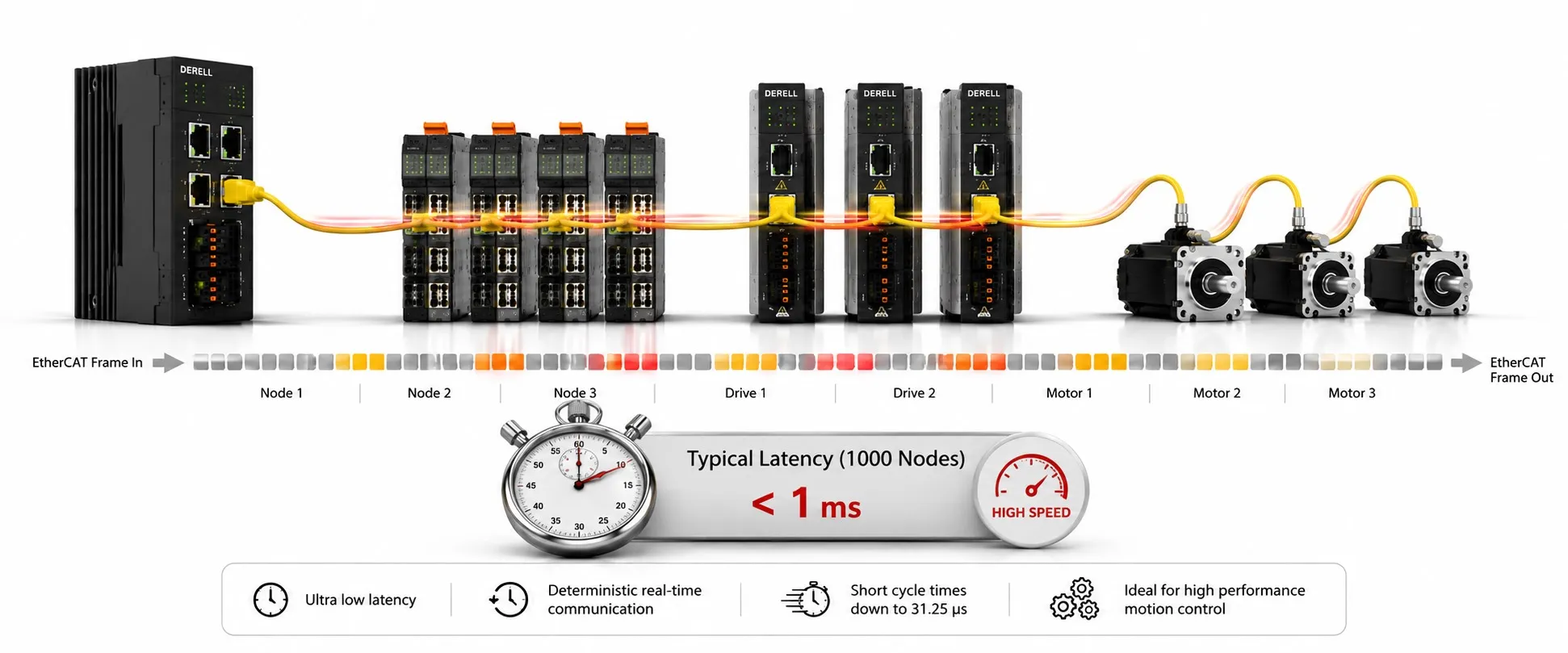
What is the latency time of EtherCAT? There is no single latency number that describes an EtherCAT machine. Engineers need to separate frame propagation, telegram serialization, communication cycle, synchronization jitter and end-to-end I/O response. EtherCAT keeps the network contribution small because SubDevices process relevant data while the frame is passing instead of receiving a complete Ethernet frame, handing it to a software stack and transmitting a new response frame.[1]
For that reason, the old shortcut “about 30 ns per slave” is not a reliable general design value. ETG.1600 gives a more useful installation-level figure: for SubDevices containing at least one 100BASE-TX or 100BASE-FX port, the typical sum of internal hardware propagation delays in both directions is about 1 µs; an LVDS-only SubDevice is around 300 ns. The exact number still depends on the ESC, PHY and port path.[2]
| Timing term | Where it occurs | Why it must be kept separate |
|---|---|---|
| ESC/PHY propagation | Inside each SubDevice as the frame crosses hardware | Hardware-specific; not the whole network response time |
| Serialization | Putting the Ethernet telegram bits onto the wire | Depends strongly on frame length and link rate |
| Cycle time | MainDevice process-data schedule | A 250 µs cycle does not imply a 250 µs physical I/O response |
| Jitter | Variation in timing from cycle to cycle | Distributed Clocks can keep synchronization well below 1 µs |
| End-to-end response | Sensor → network → controller → network → actuator | Includes local filters, controller task and actuator dynamics |
Per-device latency is a hardware path, not a universal constant
An EtherCAT frame does not wait for the SubDevice application processor to parse the complete packet. The ESC handles EtherCAT data in hardware and forwards the frame. ETG's installation guidance therefore characterizes delay primarily as a hardware propagation contribution. For 100BASE-TX/FX devices the typical round-path contribution inside a device is around 1 µs; LVDS-only devices are lower.[2]
Specific silicon can be faster. Beckhoff's ET1100 data sheet shows average single-pass forwarding/processing values in the roughly 130–305 ns range, depending on whether the path uses EBUS or MII ports and whether the frame passes through the processing unit. Those numbers are useful for an ET1100-based design, but they are not a blanket specification for every EtherCAT product.[3]
The telegram itself has a finite wire time
At 100 Mbit/s, a longer EtherCAT telegram obviously takes longer to serialize. Beckhoff's EtherCAT G comparison gives about 6.08 µs for a minimum-length 100 Mbit/s telegram and about 122.40 µs for a telegram carrying 1500 bytes of user data, including preamble and VLAN-tag assumptions used in that comparison.[4]
That is wire time, not “the EtherCAT latency”. One frame may contain process data for many devices, which is why on-the-fly processing avoids the much larger overhead of individual request/response Ethernet packets for every small I/O value.
Propagation delay is measured because the network is physically distributed
Distributed Clocks setup measures when a designated frame reaches each ESC port. The MainDevice reads those timestamps, reconstructs the network path and calculates the propagation delay from the reference clock to each DC device. The calculated delay is then written into the device's System Time Delay register so local clocks can compensate for their physical position in the network.[5]
This is why cable length and topology do affect absolute propagation time while still allowing high synchronization accuracy. The separate topology and cable-length discussions deal with those physical limits.
Latency, cycle time and jitter answer different questions
Latency asks how long information takes to move from one defined point to another. Cycle time asks how often cyclic process data is exchanged. Jitter asks how much a scheduled event moves around its intended time. A system can have a 500 µs cycle, tens of microseconds of communication delay and sub-microsecond synchronization jitter at the same time; those values are not contradictory.
This distinction is central to real-time performance. Fast communication is useful, but deterministic timing and predictable device behavior are usually more important than chasing the smallest isolated forwarding number.
Distributed Clocks attack jitter, not physics
EtherCAT Distributed Clocks synchronize local hardware clocks and compensate measured propagation delays. ETG states that the resulting system jitter can be significantly below 1 µs. A published scope example with 300 distributed nodes and 120 m of cable shows synchronization in the tens-of-nanoseconds range; that result illustrates the mechanism, not a universal guarantee for every product and installation.[6]
For coordinated servo systems, this matters because drives can act on a common time reference even if the MainDevice frame itself is not emitted at exactly the same nanosecond on every cycle. The MainDevice still has to deliver data before the relevant local SYNC event.
Published update times are system examples, not universal latency specifications
ETG's performance material gives examples such as 1000 distributed digital I/O in 30 µs, 200 16-bit analog I/O in 50 µs and 100 servo axes in 100 µs when each axis exchanges 8 bytes in and 8 bytes out.[7]
These figures show what the communication architecture can achieve under the stated data assumptions. They should not be copied into a machine specification without checking the actual MainDevice, PDO mapping, device minimum cycle times and application workload. The technical-specifications page covers those dependencies separately.
A real product example: EK1100 lists about 1 µs propagation delay
Beckhoff's EK1100 EtherCAT Coupler specifies an approximate propagation delay of 1 µs. That is a useful real-product sanity check against the old “30 ns per slave” shortcut and is consistent in scale with the ETG.1600 installation guidance for 100BASE-TX devices.[8]
It is still not the I/O response of the terminals attached behind the coupler. A digital-input filter, analog conversion or local drive control loop can easily dominate the final sensor-to-actuator timing.
An illustrative 20-node latency budget
Illustration, not a field measurement: take 20 100BASE-TX/FX EtherCAT SubDevices and, only for an order-of-magnitude estimate, use ETG.1600's typical ~1 µs two-direction internal hardware contribution per device. The aggregate device-internal propagation contribution is then on the order of 20 µs. Cable propagation and telegram serialization still have to be added.
That does not mean the network has a 20 µs cycle, and it is not a substitute for product-level timing data. A proper design uses the actual ESC/PHY path, cable lengths, telegram layout and MainDevice timing. This is exactly why the limits and constraints page separates theoretical protocol scale from practical machine timing.
EtherCAT G mainly reduces the serialization part of the budget
EtherCAT G runs at 1 Gbit/s and G10 at 10 Gbit/s. In Beckhoff's comparison, a 1500-byte-user-data telegram falls from approximately 122.40 µs at 100 Mbit/s to 12.24 µs at 1 Gbit/s and 1.22 µs at 10 Gbit/s.[4]
That is valuable when payload size dominates communication time. It does not make a sensor's conversion time or a controller algorithm ten or one hundred times faster. The complete latency budget still has application-side terms.
For motion, the useful question is usually three questions
In a high-performance motion system, ask: What is the supported communication cycle? What synchronization jitter can the drive achieve? What is the drive's application delay from process data to the internal control loop? A low frame-propagation number only answers part of that picture.
Encoder sampling, drive current-loop timing and mechanical response also matter. The encoder and servo specifications therefore belong in the same timing review as the EtherCAT network. Distributed Clocks makes those components share a precise time base; it does not eliminate their internal delay.
Why an HMI can look slow on a fast EtherCAT machine
Operator displays and SCADA systems commonly update at much slower rates than the EtherCAT field cycle. A 500 ms screen refresh does not mean the EtherCAT network has 500 ms latency. The PLC-to-HMI communication task, tag polling, historian or visualization refresh can dominate what the operator sees.
Similarly, a delayed process value can come from sensor filtering or conversion rather than the fieldbus. Diagnostics should trace the complete signal path instead of blaming the network because the last visible stage is slow.
How to report EtherCAT latency so another engineer can reproduce it
A meaningful measurement states topology, device models, cable length, PDO/frame size, cycle time, DC mode and the exact measurement points. “Latency = 80 µs” is incomplete unless the reader knows whether that means MainDevice-to-SubDevice process data, round-trip frame time, input-to-PLC variable or physical input-to-physical output.
For commissioning, combine MainDevice timing diagnostics, DC timestamps/registers, port error counters and—where end-to-end behavior matters—an oscilloscope measurement of physical I/O. That also makes comparisons with other Industrial Ethernet protocols technically defensible.
Related EtherCAT guides
References
[1] EtherCAT Technology Group, EtherCAT Technology – Functional Principle and Distributed Clocks: https://www.ethercat.org/en/technology.html
[2] EtherCAT Technology Group, ETG.1600 EtherCAT Installation Guideline, on-the-fly processing and typical hardware propagation-delay values: ETG.1600
[3] Beckhoff, ET1100 EtherCAT Slave Controller Hardware Data Sheet, forwarding-delay table: ET1100 data sheet
[4] Beckhoff, EtherCAT G, 100 Mbit/s / 1 Gbit/s / 10 Gbit/s telegram times: EtherCAT G brochure
[5] Beckhoff, EtherCAT ESC Technology – Propagation Delay Measurement: ESC Technology Data Sheet
[6] EtherCAT Technology Group, Distributed Clocks for High-Precision Synchronization: ETG Brochure
[7] EtherCAT Technology Group, Performance Overview: 1000 I/O / 200 analog I/O / 100 servo axis examples
[8] Beckhoff, EK1100 EtherCAT Coupler, propagation delay ≈ 1 µs: EK1100 technical data