
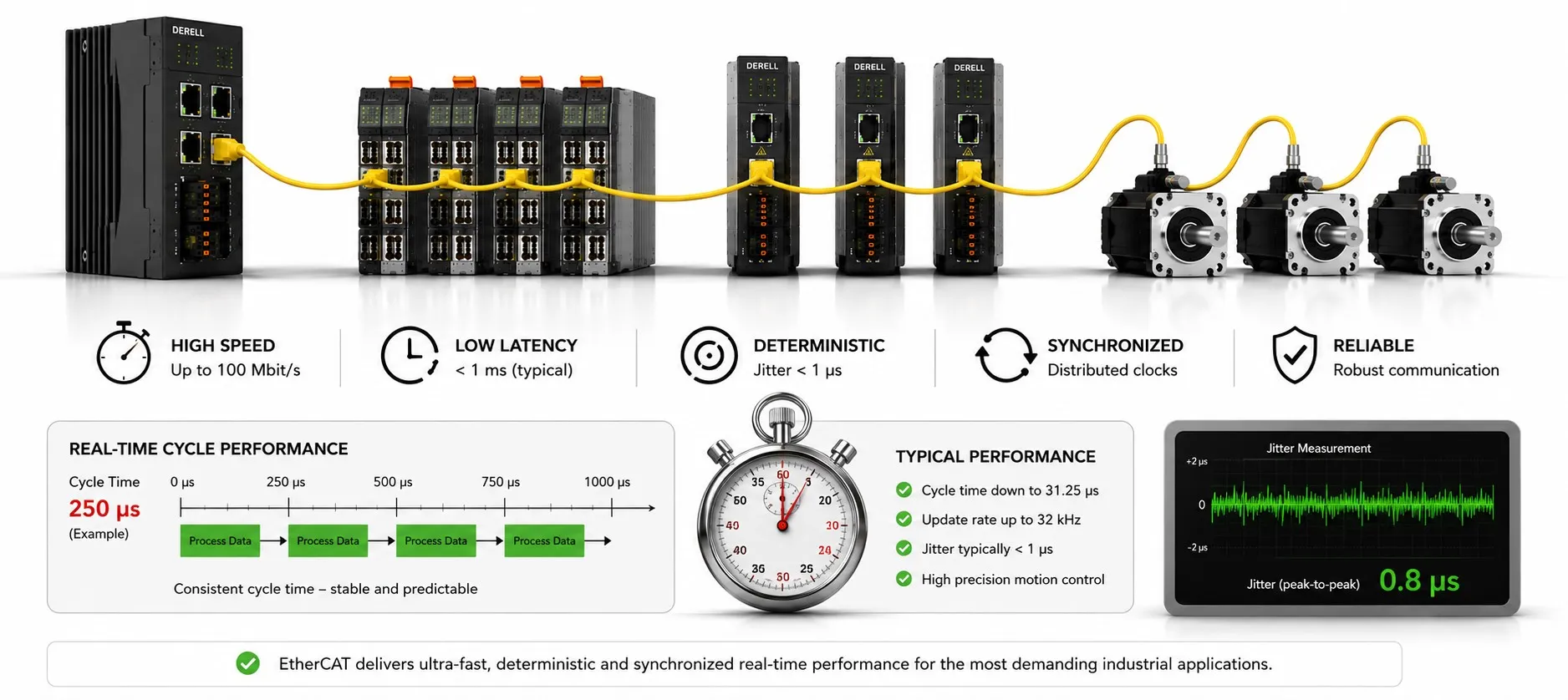
How does EtherCAT handle real-time performance?
EtherCAT combines efficient cyclic data transfer with precise local timing. It is designed to move small control-data updates predictably, while Distributed Clocks can coordinate supported devices against a shared time base. The useful result is not simply a high packet rate: it is the ability to have valid data ready when the machine needs to act. That still depends on the controller, the I/O and the application schedule. [1] [2]
This is the practical distinction between a fast network and a real-time control system. The EtherCAT architecture supports the latter, but the protocol name alone does not establish a machine’s response time. Start with an acceptance question: which physical event must produce which result, and by what deadline?
Specify the timing requirement before choosing a cycle
Cycle time is the interval between planned updates. A 250 µs interval gives 4,000 updates per second; 1 ms gives 1,000. End-to-end latency is the time between defined measurement points, such as an electrical input transition and a physical output change. Those endpoints are not the same as the departure and return of a network frame.
Jitter describes variation in a specified timing quantity. Task-start jitter, frame-transmit jitter and output-event jitter are different measurements. Synchronization error describes the offset between clocks or comparable events at different devices. A statement such as “1 µs jitter” needs a measurement point, a definition and a statistic; it is not a complete performance specification.
Two outputs can operate almost simultaneously and still both miss the required deadline. A different system may react quickly enough but have too much relative timing error between axes. Treat latency, repeatability and synchronization as separate requirements, then check that the complete installation meets all of them.
A 250 µs schedule shows where the margin goes
Consider the following illustrative schedule, not a tested machine or product specification. It assumes that an input transfer, a controller calculation and an output transfer can all be scheduled inside one 250 µs interval. Some implementations use a different sequence or pipeline data across multiple cycles. The destination’s preparation time is also an explicit assumption, not a universal EtherCAT constant.
| Time / interval | What happens in this example |
|---|---|
| 0 µs | The input is sampled against the shared time base. |
| 40 µs | The sampled input is available to the controller. |
| 60–150 µs | The control task runs and calculates the new output value. |
| 190 µs | The new output data reaches the destination process memory. |
| 20 µs | Assumed local preparation time at the destination; this is a duration, not an event timestamp. |
| 250 µs | The DC-scheduled output event takes place. |
Latest acceptable data arrival: 250 − 20 = 230 µs. With data arriving at 190 µs, the usable margin is 40 µs. Now add 50 µs of delay to the output-data path: the data arrives at 240 µs and the assumed local preparation finishes at 260 µs. The 250 µs target is missed by 10 µs.
Perfectly aligned clocks would not rescue that late update. The device might retain an earlier value, report an error or behave differently according to its mode and application settings. The timing calculation identifies a missed requirement; it does not specify a universal fault response.
There is another delay before this schedule even starts. If the input is sampled only once per cycle, an event immediately after a sample may wait almost 250 µs for the next one. Under these specific assumptions, the event-to-scheduled-output interval therefore ranges from about 250 to 500 µs, before adding sensor and physical-output delays that the example does not specify. The configured cycle and the observed response are not interchangeable.
Why on-the-fly processing helps
An EtherCAT SubDevice uses an EtherCAT Slave Controller (ESC) to read and insert data as a frame passes. Multiple small process-data areas can share a frame rather than requiring an application-level request and response from every device. This on-the-fly data path is the key to efficient use of classic EtherCAT’s 100 Mbit/s links. It avoids making every frame transfer wait for the local application program. [1]
The local program still has work to do. A fast ESC does not make a slow measurement conversion, filter or control algorithm instantaneous. This is also why EtherCAT versus ordinary Ethernet is not just a comparison of bit rates. Keep the G/G10 extensions separate from the performance of an installed classic 100 Mbit/s segment; a family name is not an automatic hardware upgrade.
A shared clock separates arrival time from action time
Distributed Clocks allow supported devices to trigger local events against a common time reference, with propagation delay taken into account. A sample or output event can therefore follow the planned clock time rather than the instant the frame arrives. This is valuable for coordinated servo motion. The important condition is that the required data must already be available before the scheduled event. [1] [14]
Check the selected mode, not just the feature list. Delta Motion explicitly notes that DC synchronization may need to be enabled and that manufacturers use different names for the operating modes. A device without DC can be part of an EtherCAT installation without acquiring the timing capability of a DC-enabled device. The device-integration check should establish which components actually sample or update from that shared time base. [2]
SYNC0/SYNC1 timing, phase shifts and the relationship between the master clock and the reference clock are implementation details that need the relevant device and master documentation. Preserve the device’s preparation-time requirement when adjusting the schedule. Choosing a smaller cycle value is not, by itself, evidence of a better configuration. [14]
Read the numbers on a real timestamp input
The Beckhoff EL1252 is a two-channel, 24 V DC timestamp input terminal. Its published data distinguishes 1 ns timestamp resolution, 10 ns plus input delay accuracy between channels, and input delay below 1 µs. These specifications describe different things. A 1 ns timestamp step does not establish 1 ns accuracy throughout the network, let alone a 1 ns response from a sensor to a motor. [5]
Timestamping preserves information about when an event happened even though the controller receives that information later. The EL1252 also specifies latch last edge; it should not be treated as an unlimited record of every intervening transition. When working with encoder output signals, check the acquisition hardware’s edge-capture capacity as well as its timing resolution. [5]
Sub-millisecond operation is a system capability, not a blanket promise
Beckhoff describes I/O response below 100 µs for its optimized XFC combination of controller, EtherCAT, software and fast I/O. That is a useful example of achievable system performance, not a guaranteed result from any combination of EtherCAT products. Keep the stated hardware and measurement scope attached to the performance specification. [4]
Oversampling is different again: a device takes multiple samples within a bus cycle and transfers them as a group. For example, ten evenly spaced samples in an assumed 1 ms cycle give a 100 µs sample interval, or 10 kS/s. A closed-loop controller consuming that block may still issue a new command only once per millisecond. More acquired samples do not automatically mean more closed-loop decisions. [4]
The same caution applies to analog inputs: transmitting the converted value faster does not establish the response of the sensor or its filtering. Identify the physical bandwidth and timing requirement first, then decide which part of the communication and acquisition chain needs improvement.
Device-to-device data still follows a configured path
It would be wrong to describe EtherCAT as either unrestricted peer-to-peer networking or as a network with no direct device-to-device transfer. With suitable process-image and FMMU configuration, an upstream producer can write data into the frame that a downstream consumer uses within the same cycle. EC-Engineer documents the ordering condition explicitly. This is a configured data relationship, not permission for every device to originate arbitrary frames. [3]
The other common path copies input data to an output area inside the MainDevice stack. In the sequence documented by acontis, the input is read in one cycle and written to the destination in the next. Thus the MainDevice/SubDevice relationship and the chosen transfer mechanism determine the data age. A claim that the master is simply bypassed misses that distinction. [6]
Protect the schedule from avoidable workload
Host execution matters. Real-time runtime support, the network driver and task scheduling belong in the design alongside the field network. acontis documents additional real-time support rather than treating normal Windows execution as sufficient. When selecting EtherCAT software and tools, check the long-duration tail of control jobs, not just an average CPU-load figure. [8] [12]
Separate cyclic data from parameter services. PDOs carry recurring targets, feedback and status; SDOs provide a different parameter-access service. Review the process-data map and avoid transferring fields that the application does not need at the fastest rate. Whether heavy parameter access affects a cyclic task depends on the master’s scheduling; neither “SDOs always cause jitter” nor “SDOs can never matter” is an adequate engineering rule. [9] [10]
A flexible topology still has a timing budget
A machine can use lines, branches or stars, but an EtherCAT star uses suitable junctions rather than an ordinary Ethernet switch. The network topology determines the physical path. Flexibility does not mean that cable and device transit times disappear. Recheck the timing budget and observations after changing that path. [7]
Cable redundancy is a separate availability feature. A ring returning to a second master port needs appropriate software support and configuration; Delta Motion explicitly requires enabling Cable Redundancy on the RMC. It is not controller redundancy, and it is not a promise of uninterrupted operation through every fault. Include the supported fault response in the installation’s limits and acceptance criteria. [7]
Validate at the point where the requirement exists
Choose the evidence that matches the question. Electrical input-to-output response, relative timing between outputs and controller execution time need different observations. A slowly refreshing HMI display is not a bus-latency measurement. EC-Engineer, for example, documents a 250 ms refresh for some monitoring charts; the display interval is separate from the network cycle. [12]
Check freshness and communication health. In the documented TwinCAT interface, WcState distinguishes valid from invalid real-time communication, and input values can remain at their previous valid values after an invalid exchange. A stable number is therefore not proof of a fresh sample. Working Counter, missing-frame, watchdog and DC-not-in-sync indications provide distinct evidence. Use them together when troubleshooting timing problems, rather than treating an OP indication as a complete timing certificate. [11] [13]
A useful acceptance record identifies the devices and firmware, operating modes, configured cycle, process-data size, workload, observation duration and sample count. Report minimum and maximum observed times, the chosen jitter statistic and any deadline misses. This is a suggested engineering record, not a universal manufacturer acceptance standard.
Observe conditions representative of production, but use an authorized test arrangement for intrusive checks. Do not bypass protective circuits or disconnect a working motion network merely to test a claim. A measurement log with no failures describes that observation period; it is not a proof for every possible operating condition. For physical timing measurements, include the trigger method, probe effects and measurement uncertainty.
The practical result: EtherCAT provides an efficient transfer mechanism and a shared timing framework. A real machine still has to demonstrate the whole chain: a valid input, a completed calculation, output data available before its deadline and the required physical event. Measuring one of these does not verify the other three.
References and scope
Product-specific figures apply only to the named device or software context. The 250 µs schedule is an educational assumption, not a machine test result.
[1] Beckhoff — EtherCAT: The technology in detail — On-the-fly processing, ESC hardware, distributed clocks and the requirement to deliver data before the DC output event.
[2] Delta Motion — Distributed Clock Synchronization — DC support, feedback timing and the need to select a supported synchronization mode.
[3] acontis — EC-Engineer 4.1, Configuration Mode — Section 5.2.7: ordering constraints for in-cycle SubDevice communication; sections 5.2.8 and 5.3.10: DC configuration.
[4] Beckhoff — XFC: eXtreme Fast Control Technology — Sub-100 µs response as an optimized-system capability; distinction between timestamping and oversampling.
[5] Beckhoff — EL1252 technical data — EL1252: 1 ns timestamp resolution, 10 ns plus input delay accuracy between channels, sub-1 µs input delay and latch-last-edge capability.
[6] acontis — EC-Engineer Web V2.4: SubDevice to SubDevice copy — The usual two-cycle MainDevice copy path, distinguished from downstream in-cycle communication.
[7] Delta Motion — EtherCAT Network Topologies — EtherCAT junctions, a second-port ring and the RMC Cable Redundancy setting; RMC-specific topology restrictions are not generalized to every master.
[8] acontis — EC-Engineer 4.1: Real-time Support — Section 8.11: distinction between ordinary Windows operation, real-time support and optimized link layers.
[9] Delta Motion — EtherCAT Process Data Object (PDO) — Cyclic targets and feedback, PDO mapping and device-supported data layouts.
[10] Delta Motion — EtherCAT Service Data Object (SDO) — SDO parameter access as a service distinct from cyclic PDO exchange.
[11] Beckhoff Information System — WcState — WcState values 0/1, retained input values after invalid communication and InputToggle.
[12] acontis — EC-Engineer 4.1: Diagnosis — Section 6.2.4: bus load, CPU jobs and duration distributions; display refresh intervals are separate from bus timing.
[13] Beckhoff Information System — Additional Diagnostic information — Separate diagnostic indications for Working Counter, missing frames, watchdog and DC-not-in-sync conditions.
[14] Beckhoff Information System — EtherCAT Distributed Clocks — DC reference clocks, offset and propagation-delay compensation; SYNC0/SYNC1, local events and shift-time relationships.