
What is EMI filter?
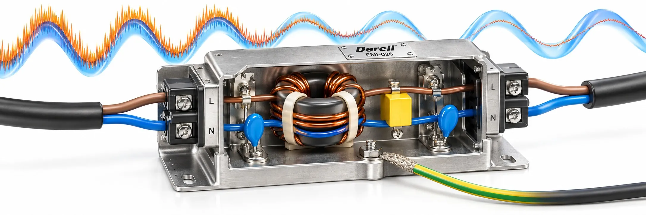
A quieter power connection starts with the right noise path
An EMI filter reduces high-frequency interference carried by wiring. A mains input filter passes the intended 50 or 60 Hz supply while attenuating unwanted higher-frequency components. It can reduce noise entering or leaving equipment, but its performance depends on frequency, circuit impedance and installation.
In a variable frequency drive, PWM switching and fast IGBT transitions create disturbances. The carrier frequency affects the noise spectrum; it does not describe every frequency present. Wiring and stray capacitance provide paths into other circuits.
Three labels, two different meanings
EMI is the interference; EMC is electromagnetic compatibility. Suppliers often use “EMI filter” and “EMC filter” for the same mains-filter family. RFI focuses on radio-frequency interference. An electromagnetic filter supports noise control; fitting one does not establish compliance for an entire machine. Emissions and immunity must be assessed at system level.
Identify the noise before choosing the components
Differential-mode noise circulates between conductors. Class X capacitors connect across them and work with suitable series inductance. Common-mode noise travels in the same direction along conductors, returning through chassis connections and stray capacitance. Common-mode chokes and Class Y capacitors address that path. Components connected to mains require the appropriate safety classification; an ordinary capacitor is not a safe substitute.
Reading the 20 dB example: at a given frequency, under the same impedance and measurement conditions, reducing noise voltage from 1 V to 0.1 V gives 20 dB attenuation. The wanted supply has not fallen to one tenth. A datasheet insertion-loss curve describes specified test conditions; it is not a promise of identical attenuation everywhere in a cabinet.
Input filtering and motor-side filtering do different jobs
Drive input filters belong on the supply side of the frequency inverter. A general mains filter must not be moved to its U/V/W motor terminals. Motor-side requirements call for a suitable output filter or output reactor, selected according to the drive manual and cable installation.
An input reactor, a DC bus choke and a harmonic filter also have distinct roles. An EMI filter does not automatically correct low-order supply harmonics. Sharing a cabinet does not make these components interchangeable.
Check the rating, then check the mounting
Match voltage, input current, phase configuration, ambient temperature and leakage current. Motor kW alone is insufficient; use the drive's input rating and the manufacturer's recommended pairing. Y capacitors contribute leakage current, alongside the drive and motor cable. Check compatibility where an RCD is installed. Disconnecting protective earth is never a remedy.
Keep the filter-to-equipment connection short and separate filtered wiring from unfiltered wiring. Otherwise, noise can couple around the filter. Bond the metal housing to the conductive mounting surface as specified. Grounding provides protection; connection length and inductance also matter at high frequencies.