
what is emergency stop?
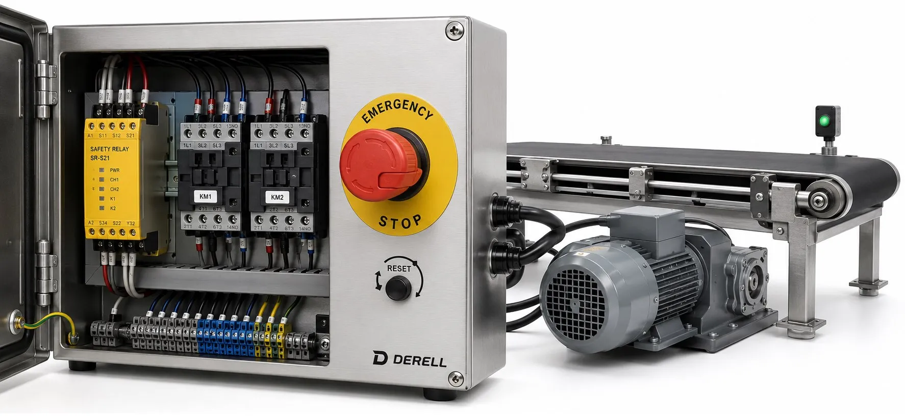
Emergency stops explained: what an E-stop does
An emergency stop is a manually initiated safety function intended to stop a hazardous machine movement or process. Its purpose is to reduce an existing or developing danger as quickly as possible, without creating another hazard. The familiar red mushroom pushbutton is the operator interface; the complete function also includes the equipment that processes the demand and brings the machine to the required condition.
A pressed E-stop does not prove that everything has stopped instantly or that every energy source has been disconnected. Stopping time, braking behaviour and remaining energy depend on the machine. Emergency stopping supplements other protective measures, including guards and protective devices.
Emergency stop versus an ordinary stop command
An ordinary stop button is used during normal operation. An emergency stop addresses a hazardous situation and must take priority over the relevant start and normal operating commands. Its operation must not defeat other safety measures.
The emergency stop demand remains active until it is deliberately reset. Releasing pressure on the actuator must not simply cancel the stop request. This maintained demand is one reason an E-stop cannot be treated as an ordinary momentary pushbutton with a different coloured cap.
Recognising and positioning the actuator
An emergency stop pushbutton has a red actuator and, where a background is provided, a yellow background. The common mushroom shape makes the actuator easy to operate quickly. Blue is not the correct identification colour for an emergency stop actuator.
Emergency stop pushbuttons commonly latch when operated and require an intentional action, such as twisting or pulling, to release them. Selection must consider the mechanism, contact characteristics, environmental conditions and applicable product requirements.
Devices need to be visible and readily accessible from the positions where they may be needed. On a production line with several stopping zones, the equipment affected by each E-stop must be clear. A properly designed rope-pull arrangement can provide emergency stop access along an extended conveyor.
From the button to the stopping action
Operating the device sends a demand to the safety-related control system. A suitable safety relay, safety controller or another validated architecture processes that demand. Contactors, drive safety functions, valves or other final elements then produce the specified machine response.
For devices using electrical contacts, direct-opening normally closed contacts are an important feature. However, the presence of an NC contact or two input channels does not establish the safety performance of the complete function. Relevant wiring faults, output failures and feedback arrangements also have to be considered.
The roles of relays and contactors differ, and a standard relay is not automatically equivalent to a safety relay. Similarly, connecting an E-stop to an ordinary PLC input and writing a stop instruction does not, by itself, demonstrate the required safety performance.
Why immediate power removal is not always the right stop
Stop category 0 removes power to the relevant machine actuators immediately. It is described as an uncontrolled stop because the drive does not perform a powered, controlled deceleration. A rotating assembly may continue moving while its stored kinetic energy is dissipated.
Stop category 1 retains power long enough to achieve a controlled stop, then removes power to the relevant actuators. This allows a defined deceleration or braking action to form part of the stopping process.
The machine risk assessment determines whether an emergency stop uses category 0 or category 1. Category 2, which retains actuator power after a controlled stop, is not the emergency stop category used for this purpose. These stop categories must also be distinguished from the B, 1, 2, 3 and 4 control-system categories used in ISO 13849.
Resetting the E-stop must not restart the machine
Unlatching an emergency stop device or resetting the function must not automatically initiate a restart. Reset makes restarting possible once the required conditions are satisfied; starting requires a separate, deliberate action.
The hazard that caused the stop must be resolved before the device is reset. Depending on the control architecture, an additional reset or acknowledgement may be required. Where the affected area cannot be checked from the reset position, further measures must be assessed. Turning the actuator does not establish that the entire danger zone is clear.
For example, an operator may press an E-stop after noticing a conveyor jam. Releasing the device must not cause the belt to resume moving. Resolving the fault, completing the necessary intervention procedure and intentionally restarting production are distinct steps.
Emergency stopping with a variable frequency drive
A normal STOP input on a variable frequency drive must not be assumed to provide a safety function. The drive's documented safety capabilities and the requirements of the entire machine determine the implementation.
Safe Torque Off, or STO, prevents the drive from generating motor torque. It does not, by itself, provide active braking or electrical isolation. A moving motor may coast, while gravity or another external force may continue to move the mechanism.
Safe Stop 1, or SS1, combines a controlled stopping process with subsequent activation of STO. Its implementation and monitoring requirements depend on the equipment and safety design. An emergency stop message on the drive display is diagnostic information; the message alone does not establish that the complete safety function has been correctly implemented.
Are light curtains and safety sensors emergency stop devices?
An emergency stop is initiated by a person's deliberate action. A safety light curtain, interlocking device or safety scanner can initiate a protective stop automatically when its defined conditions occur. These functions can share parts of a safety control system, but they serve different purposes.
A conventional product-detection photoelectric sensor is not suitable for personnel protection merely because it can trigger a stop command. Intended use, safety capability and the performance of the complete protective function must be established.
A stopped machine may still contain hazardous energy
An E-stop is not a substitute for the energy isolation required for maintenance. Supply voltage, a charged drive DC bus, compressed air, hydraulic pressure, springs and suspended loads can remain hazardous after motion stops.
Maintenance, cleaning and access to dangerous parts require the isolation procedure appropriate to the task. This can include disconnecting energy sources, preventing reconnection, lockout/tagout, controlling stored energy and verifying the safe condition. Emergency switching off, which addresses electrical hazards, is also a different function from emergency stopping of machinery.
Standards and verification: assess the complete function
ISO 13850 addresses emergency stop design principles. IEC 60204-1 covers machinery electrical equipment and associated stopping requirements. Depending on the application, ISO 13849-1/-2 or IEC 62061 is used for safety-related control-system design and verification, while IEC 61800-5-2 addresses drive safety functions. Machine-specific standards must also be considered.
A rating on one pushbutton, relay or drive does not establish the performance of the whole installation. The input device, logic, final elements and actual machine response must be evaluated together. Checks include accessibility, retention of the stop demand, the equipment affected and prevention of automatic restart. Test methods and intervals follow the equipment instructions and risk assessment.