
what is AVR function for vfd?
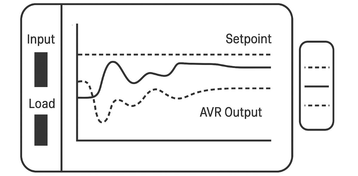
AVR – Automatic Voltage Regulation is a VFD function that reduces the effect of input-supply or DC-bus voltage variation on the motor-voltage command produced by the inverter.
A simple way to understand it is: “My DC bus has moved, but I still want the motor to receive approximately the voltage that the motor-control algorithm requested.”
AVR should not normally be described as a controller that holds one fixed motor voltage at every operating speed. The required motor voltage is already determined by the V/Hz curve, motor model and control method.
The AVR function attempts to make the inverter produce that commanded voltage more consistently despite changes in supply or DC-bus voltage.
For example, if a 400 V / 50 Hz motor is operating at 25 Hz under a conventional V/Hz pattern, the requested motor voltage may be roughly half rated voltage. AVR does not force the motor to 400 V. It attempts to maintain the voltage appropriate for that 25 Hz operating point.
How does AVR work?
In a typical VFD, incoming AC power is rectified into a DC link. The inverter stage then switches this DC voltage through its power semiconductors to create the PWM motor output.
When mains voltage changes, DC-bus voltage normally changes as well.
With AVR active, the control system accounts for the actual DC-bus level and adjusts PWM modulation or pulse width so that the required motor-voltage command is produced more consistently.
Yaskawa describes its AVR function in essentially this way: PWM pulse width is adjusted according to DC-bus level in order to maintain the desired output voltage as bus voltage changes.
How should the existing animation be read?
The existing OtomasyonAVM animation is retained unchanged because its basic idea is useful: the supply/DC-bus condition varies while AVR attempts to keep the commanded motor-voltage level more stable.
Changing trace: represents supply/DC-bus variation.
More stable trace: represents the compensated motor-voltage command.
Does AVR change output frequency?
Frequency is not the primary variable controlled by the standard VFD AVR function.
Motor frequency comes from the speed reference, acceleration/deceleration logic and motor-control algorithm. AVR mainly corrects the voltage-generation side of the inverter.
If the drive has a 30 Hz output-frequency command, AVR normally does not turn that into 35 Hz because line voltage changed. Instead, it attempts to produce the voltage commanded for the 30 Hz operating point despite changes in the available DC-bus voltage.
AVR and the V/Hz curve
The V/Hz curve determines how much motor voltage should be commanded at a particular output frequency.
AVR then helps the power stage reproduce that requested voltage even when the supply changes.
A useful simplified example is:
V/Hz curve: requests 200 V at 25 Hz.
DC bus: changes because mains voltage changes.
AVR: modifies PWM modulation to keep the motor output near the 200 V command.
They work together, but they are not the same function.
AVR and IR Compensation are different
IR Compensation corrects for the voltage drop associated with motor current flowing through stator resistance, particularly at low frequency.
AVR compensates primarily for changes in supply/DC-bus voltage.
A simple distinction is:
AVR: “My supply or DC bus changed.”
IR Compensation: “Motor current created an I × R voltage drop in the stator.”
Both affect motor voltage, but they solve different problems.
Is AVR the same as Torque Boost?
No. Torque Boost adds voltage in the low-frequency region to help maintain motor flux and starting torque.
AVR is not primarily a torque-boost function. It compensates the requested motor-voltage output against supply/DC-bus variation.
If a motor is weak at low speed, the correct subjects to investigate include V/Hz pattern, IR compensation, torque boost, motor data and vector control—not simply increasing or disabling AVR.
Can AVR compensate for a deep voltage sag?
Only within the physical capability of the drive.
A normal VFD cannot create unlimited motor voltage when DC-bus voltage is too low. AVR is not a step-up converter with unlimited boost capability.
If the bus falls below the level required to create the commanded output voltage, motor voltage will eventually fall and the drive may reach its undervoltage threshold.
Persistent undervoltage should therefore lead to checks of the mains supply, transformer, cables, contactors, fuses, incoming connections and DC-bus level—not endless AVR parameter changes.
What happens when input voltage rises?
This is one of the easiest AVR cases to visualize.
If a motor is rated for 400 V and the supply rises to 420 or 430 V, an appropriate AVR implementation can reduce PWM modulation so that the motor-voltage command remains closer to the configured motor/base voltage.
With AVR disabled, output voltage in some VFD designs follows DC-bus changes more directly.
Manufacturer documentation from Hitachi, INVT, Delta and TECO all describes AVR in broadly this manner.
Does AVR compensate for load changes?
Not in the same sense as a motor-speed regulator or process controller.
A load increase can increase motor current and the internal voltage drops of the motor. Other functions such as IR compensation, torque boost, slip compensation, vector control and speed feedback are designed to address those effects.
The standard AVR function is primarily concerned with keeping the commanded motor voltage less sensitive to supply/DC-bus variation.
AVR is not process PID
A pressure, flow or temperature loop that reads a sensor and changes motor speed is a process PID controller.
AVR operates inside the power conversion and motor-voltage generation process.
Both functions may exist in the same VFD, but they solve completely different control problems.
Is AVR an energy-saving function?
Energy saving is not the primary purpose of AVR.
Some drives provide a separate Automatic Energy Saving function that reduces motor voltage or flux under light-load conditions to reduce losses.
AVR performs a different task: it stabilizes the commanded motor voltage against DC-bus/input-voltage variation.
Some VFD manuals list AVR and Energy Saving as separate adjacent parameters, which is a useful reminder not to mix the two.
Why can AVR be disabled during deceleration?
Some manufacturers provide AVR selections such as:
• Enabled continuously
• Disabled
• Disabled during deceleration
During deceleration, regenerative energy can raise DC-bus voltage. Manufacturers handle this region differently depending on their inverter control strategy.
There is therefore no universal rule saying AVR must always be enabled or always disabled during deceleration. The manual for the actual drive should be followed.
Can AVR interact with harmonic filters?
Yes, in more specialized systems.
Yaskawa has documented cases where the changing DC-bus condition produced by certain harmonic input-filter configurations can interact with the drive's AVR response and create current oscillation.
In such cases, manufacturer-level parameters such as the AVR response/filter time may require adjustment.
This is not normally a user parameter to change casually; large-drive and harmonic-filter applications should follow the manufacturer's engineering guidance.
VFD AVR vs generator AVR
The abbreviation AVR – Automatic Voltage Regulator is also widely used in alternators and generators.
A generator AVR controls excitation to regulate generator terminal voltage.
A VFD AVR works inside the inverter's voltage/PWM control process.
The abbreviation is the same, but the hardware and control principles are different.
Should AVR normally be enabled?
Many general-purpose VFDs ship with AVR enabled because it improves immunity to normal line-voltage variation.
I would not disable it simply as an experiment. First check what AVR means in the exact drive and control mode being used.
Special harmonic-filter systems, specific deceleration behaviour or manufacturer instructions can justify a different setting, but the factory configuration is usually the best starting point.
Editor's Note – how I look at AVR in the field
Before changing AVR parameters, I want to know what the mains and DC bus are actually doing.
If a nominal 400 V supply collapses badly under load or one phase is already low, I do not expect AVR to repair the electrical installation. I check supply wiring, transformer, contactors and voltage drop first.
I also verify the motor base-voltage setting. If a 380 V motor has been entered as a 415 V motor, the voltage-control problem started before AVR even became relevant.
If the motor feels weak at low speed, AVR is not my first suspect. I look at the V/Hz curve, IR compensation, torque boost, motor current and motor identification.
The simplest useful description of AVR is this: it helps separate the motor-voltage command from ordinary changes in the available DC-bus voltage.
And when a drive is actually tripping on undervoltage, I stop tuning and start measuring the power supply.
What should you read next?
To understand the voltage target used by AVR, continue with V/Hz Curve. To understand where the available inverter voltage comes from, continue with DC Bus.
For low-speed stator-voltage compensation, read IR Compensation. For the complete drive knowledge tree, return to What Is a VFD?.
Related OtomasyonAVM sections
For real VFD products, continue to AC Drives / VFDs. For filters and surrounding drive hardware, see VFD Accessories.
External technical references
For a manufacturer explanation of AVR compensating DC-bus variation through PWM pulse-width adjustment, see Yaskawa's technical application note. INVT Goodrive documentation also defines AVR as a function used to reduce the effect of bus-voltage fluctuation on inverter output voltage.