
What is a MOSFET?
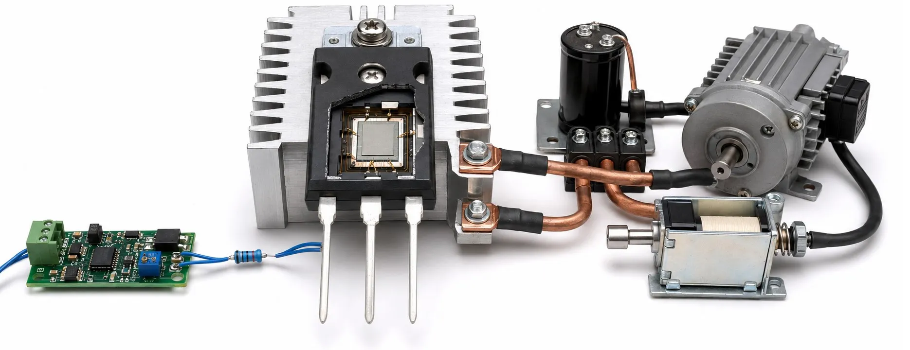
What is a MOSFET, and how does it work?
Dear colleagues,
MOSFET stands for Metal-Oxide-Semiconductor Field-Effect Transistor. It is a type of transistor used to amplify electrical signals or switch load current. Its operation is controlled by the electric field produced by the voltage between its gate and source terminals.
MOSFETs appear in far more than power boards. CMOS integrated circuits, microcontrollers and microprocessors also contain large numbers of them. A tiny transistor inside a processor and a power MOSFET carrying motor current share the same basic principle, but their dimensions, ratings and operating conditions differ substantially.
What do gate, drain and source mean?
Gate: The control terminal. The important quantity is gate-to-source voltage, VGS, rather than gate voltage measured against an arbitrary ground. If the gate is at 10 V and the source is at 8 V, VGS is only 2 V.
Drain and source: The terminals that carry load current. In a conventional N-channel switching arrangement, with the drain more positive than the source, conventional current flows from drain to source. Electron movement is in the opposite direction. Never assume that every device has the same pin order or the same connection to its exposed metal tab.
A thin insulating layer separates the gate from the semiconductor. This gives the device very low steady-state gate current. However, the gate behaves like a capacitor that must be charged and discharged, so switching requires current from the driver. A series gate resistor and a suitable gate-to-source resistor help control transitions and maintain the intended off state.
N-channel, P-channel and operating types
An enhancement-mode N-channel MOSFET is normally off when VGS is near zero and turns on with a suitable positive VGS. An enhancement-mode P-channel MOSFET turns on when its gate is sufficiently negative relative to its source. Positive and negative always refer to the source terminal.
A depletion-mode MOSFET behaves differently: it can conduct at VGS = 0 and is turned off with an appropriate gate-to-source voltage. Therefore, “all MOSFETs need gate voltage to turn on” is an incorrect generalisation. Identify the channel type, operating mode and pinout before choosing or connecting a device.
MOSFET animation: channel switching and current
The green channel represents conduction established by a suitable gate-to-source voltage. The moving white dot represents conventional current from drain to source, rather than the movement of an individual electron.
The illustration repeats with 600 ms on and 400 ms off. Actual switching speed, semiconductor structure, the body diode and gate charging are omitted from this simplified animation.
Threshold voltage does not mean fully on
The data sheet parameter VGS(th) identifies the gate-to-source voltage at which the device reaches a specified small test current. It does not establish that the MOSFET can carry the intended load with low losses. For switching applications, check the VGS conditions under which RDS(on) is guaranteed. A device specified only with 10 V gate drive should not automatically be considered suitable for 3.3 V control.
The description logic-level MOSFET is also insufficient on its own. If your controller provides 3.3 V, check for a guaranteed on-resistance at an appropriate gate voltage. Respect the relevant DC voltage limits. An N-channel high-side switch may require a dedicated driver because its source voltage rises as the switch turns on.
Why does a MOSFET get hot?
An conducting MOSFET is not an ideal short circuit. Approximate conduction loss is P = I² × RDS(on). For example, a continuous current of 10 A through an on-resistance of 20 mΩ at the relevant operating conditions produces approximately 2 W of loss. Using Ohm's law, the voltage drop is approximately 0.2 V. Resistance changes with temperature; PWM operation also requires duty cycle and switching losses to be considered.
Gate charge, driver current and switching frequency influence transition losses. Increasing the frequency does not automatically improve efficiency. A large current rating on a data sheet does not establish that a small circuit board can carry that current continuously. Cooling, package limits, copper area and the safe operating area must be considered together.
The body diode and inductive loads
A typical discrete power MOSFET includes a body diode. In an N-channel device, its forward direction is from source to drain. Therefore, turning the gate off does not block current in both directions. Consider the orientation of the diode and the voltage polarity in the actual circuit.
Switching a motor, coil or inductor can produce a voltage transient when its stored energy is released at turn-off. Choose a suitable freewheeling path, diode or alternative clamping circuit for the load and topology. The MOSFET's body diode does not meet every protection requirement in every circuit.
Where are MOSFETs used?
MOSFETs can switch LED loads, control DC motors and operate in power converters or certain PLC output circuits. Connecting a power stage to sensor and control electronics requires suitable drive circuitry. Where electrical separation is needed, an optocoupler or another isolation solution may be incorporated into the driver arrangement.
In a switched mode power supply containing a transformer, a MOSFET may act as the switching element. A triac or thyristor has different triggering and turn-off behaviour. These components are not direct substitutes for a MOSFET.