
What are the COM, VΩ, mA and 10 A inputs on a multimeter for?
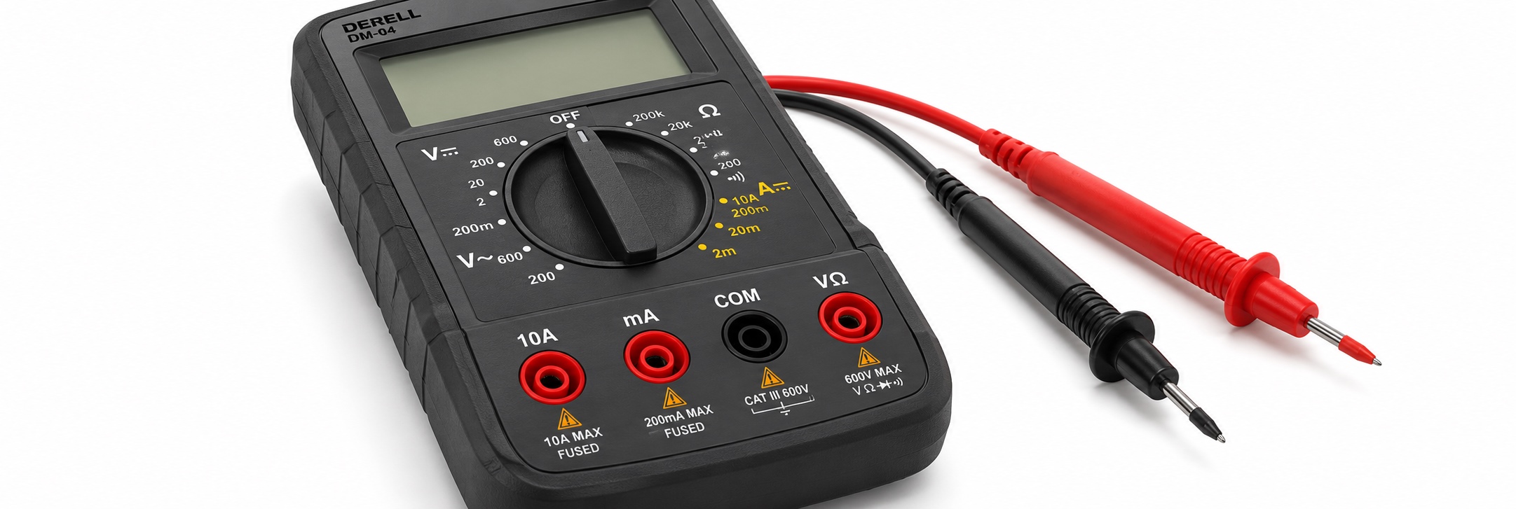
What are the COM, VΩ, mA and 10 A inputs on a multimeter for?
The input jacks connect the test leads to different circuits inside the multimeter. COM is the common connection. VΩ normally serves voltage, resistance and several other functions. The mA and A inputs route current through the meter’s current-measuring circuit.
This physical connection matters just as much as the dial setting. If the red lead remains in a current jack, turning the selector to volts may leave a low-resistance path between the probes. That is why changing measurements involves checking both the function and the lead position.
The explanation below covers a common handheld digital multimeter. Your instrument’s markings and manual take priority: some meters combine functions in one jack, while others have no direct current input.
The four common inputs at a glance
| Input | Usual lead | Purpose | Important limit |
|---|---|---|---|
| COM | Black | Common return and measurement reference. | It is not automatically protective earth or a safe point to touch. |
| VΩ | Red | Voltage, resistance and other supported functions. | The selected function determines how the input is used. |
| mA / μA | Red | Direct measurement of smaller currents. | Maximum current and fuse protection are model-specific. |
| A / 10 A | Red | The meter’s higher-current measurement path. | Check current, duration, voltage and protection ratings. |
Why the current input must not go across a supply
In normal voltage mode, the meter measures the potential difference between two points through a high-impedance input. For direct current measurement, current must pass through the meter. Its current input therefore includes a low-resistance measuring path, commonly using a shunt.
Placed in series with a suitable circuit, that path lets the meter act as an ammeter. Placed directly across a voltage source, it can create a short circuit. Selecting a voltage range does not necessarily disconnect the current jack internally.
The guides to current measurement methods and measuring current with a multimeter explain the series connection in more detail.
COM is a reference, not automatically earth
COM means common. On a battery-powered handheld meter, it provides the reference connection for the measurement. It does not mean that the connected point is at earth potential, and it should not be confused with protective earthing.
During a DC voltage measurement, the display indicates the red probe’s potential relative to the black probe. Reversing the probes across a suitable low-voltage battery normally reverses the sign on a digital meter. A negative reading therefore describes polarity relative to the chosen reference; it is not automatically a fault.
This is useful when learning how voltage is measured or identifying adapter connector polarity. The permissible voltage between terminals and from terminals to earth must still be respected.
VΩ: one jack, several different functions
The VΩ label identifies voltage and resistance functions. It does not select between them. The dial and function buttons determine what the meter does with that input.
For voltage, select the appropriate AC or DC function. Some instruments require a button press to change between them. Follow the separate guides for AC voltage measurement and DC voltage measurement.
Many meters use the same jack for resistance, continuity and diode testing. Capacitance, frequency and temperature may also use it, depending on the instrument and accessories.
Sharing a jack does not mean sharing a test procedure. Resistance, continuity, diode and capacitance tests require the test object to be de-energized, with stored energy safely addressed. A voltage rating printed near the socket does not authorize applying that voltage in every function.
mA and μA inputs: small currents need the right range
One ampere equals 1,000 milliamperes. A 12 mA signal is 0.012 A. A suitable mA range can resolve small changes that may be difficult to see on the high-current range. The maximum permitted current is not universal: read the rating beside the jack and the manual.
A 4–20 mA sensor loop is a typical application, provided the instrument and connection method suit the loop. Do not confuse mA with mV. These represent current and voltage respectively; the guide to volts, amperes and watts explains the underlying quantities.
A current measurement also changes the circuit slightly. The meter’s added impedance produces a voltage drop called burden voltage. In a low-voltage circuit or a current loop with limited voltage headroom, this can affect operation. Better display resolution alone does not guarantee the most suitable measurement range.
What the 10 A marking does—and does not—promise
The marking identifies a high-current measurement capability under specified conditions. It does not mean that the meter supplies 10 A or automatically limits current to 10 A. It also does not establish how long that current may be measured.
Check the permitted continuous current, any timed overload allowance and any required cooling interval. These vary by model. A time limit quoted for another meter is not a safe substitute for your own instrument’s instructions.
If the expected current could exceed the meter’s limits, do not connect it merely to find out. A suitable clamp meter or another measurement system may be required. Motors illustrate the issue: their starting current can be substantially different from the steady running current.
Autoranging does not move the test lead
Autoranging normally selects a suitable range within the chosen measurement function. It does not transfer the red lead from the mA jack to VΩ. Automatic AC/DC detection, where available, is another separate feature.
Some meters warn about a mismatch between the input jack and selected function. Others use shutters or mechanical interlocks. These features are not universal, and silence is not confirmation that the setup is correct.
Three everyday examples
Checking battery voltage: Use COM and the specified voltage input with DC voltage selected. The current jack is not needed. See battery voltage measurement for interpreting the result.
Checking the current drawn from an adapter: Current is measured while the intended load is operating, using a suitable series connection or another appropriate method. Do not place a current input across the adapter output. A 2 A output rating describes available capacity under specified conditions, not a current that always flows.
Checking an isolated fuse for an open element: Use the jack and function specified for resistance or continuity, usually VΩ and COM. This is not a job for the mA input. The guide to testing fuses and broken cables explains the distinction.
Why voltage measurement may work when current measurement does not
A blown current-input fuse can interrupt the current path while leaving voltage measurement operational. However, an incorrect setting, a lead problem or no current flowing in the test circuit can produce a similar complaint. A zero reading alone does not identify the fault.
The purpose of a fuse includes safely interrupting fault current. A replacement must meet the manufacturer’s specification for voltage, current, breaking capacity, operating characteristic and dimensions. Matching only the ampere rating is insufficient. Never bridge a fuse with wire or foil.
FUSED indicates fuse protection; UNFUSED indicates that the input lacks it. If protection is unclear, consult the manual. Any inspection or replacement must follow the manufacturer’s maintenance procedure with the instrument disconnected from all circuits.
Current rating and CAT rating answer different questions
A 10 A rating concerns current measurement. The measurement category and associated voltage rating concern suitability for the electrical environment, including transient hazards. A circuit carrying a small current can still be at a hazardous voltage.
Also check the rating of the particular input being used. The largest voltage printed on the front panel does not necessarily apply to every terminal or function. Instrument, input and test leads must all suit the measurement. See True RMS and CAT ratings for more detail.