
What should I pay attention to when choosing a heat controller?
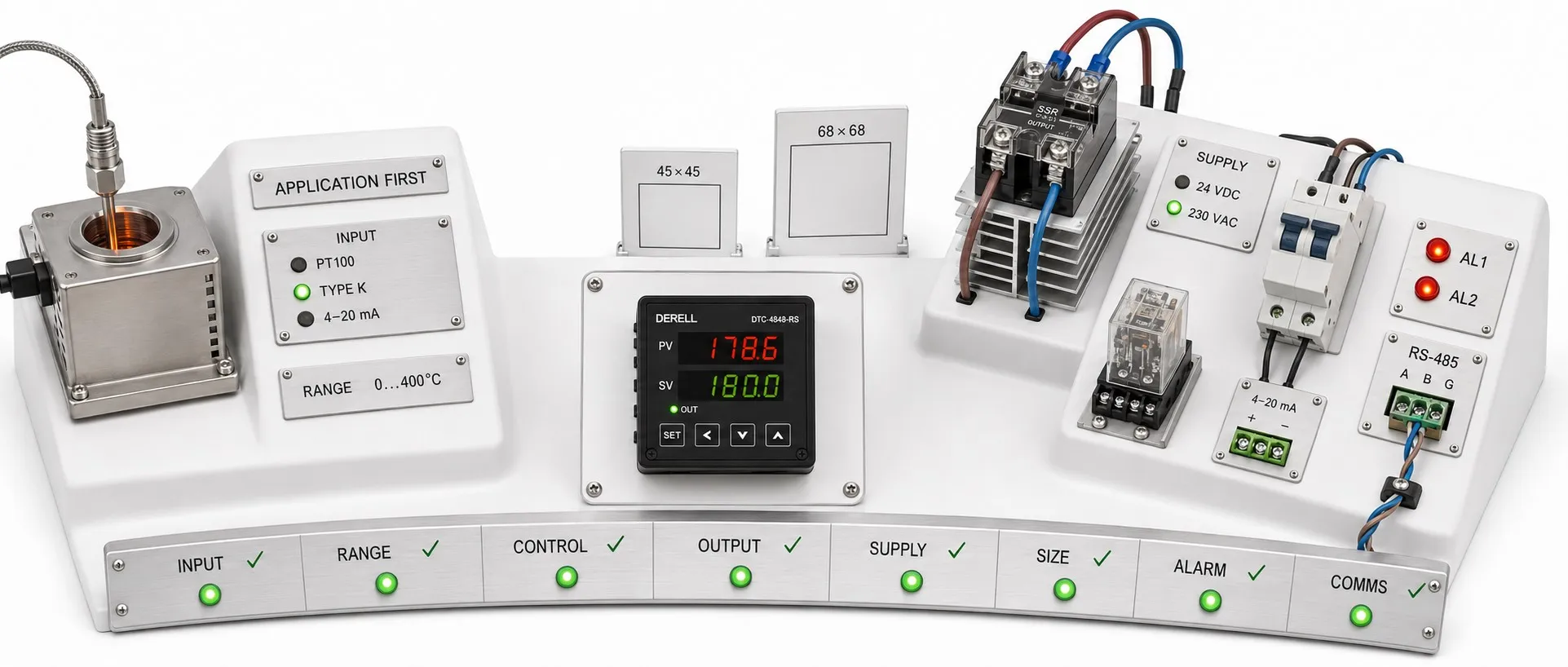
Define the process before choosing the model code
Hello, the right temperature controller must do more than display the required temperature. Its sensor input, control method, output hardware, power circuit and fault behavior must suit the same application. Two visually identical controllers in one series may have different supplies or outputs; select by the complete model code.
Editor's note: “PID,” “universal input” and “SSR output” are not complete specifications. Universal input may not cover every sensor. An SSR drive output generally controls an external power device; it does not supply heater power. Read the input/output tables and wiring diagram as carefully as the feature names.
Specify temperature, tolerance and time together
Write down the target, permitted temperature deviation, acceptable overshoot and required warm-up time. Instead of “180 °C control,” specify something like “operate at 180 °C, remain within ±2 °C at steady state, and avoid a startup temperature that damages the product.” This is an example process requirement, not a promised controller performance.
Maximum measurement capability differs from the adjustable operating range. The usable range may change with the selected sensor type. The controller, sensor, cable and probe sheath must all suit the temperature conditions. A wide catalog range does not mean identical accuracy or control performance throughout.
Do not confuse resolution with accuracy
A display with 0.1 °C resolution does not establish ±0.1 °C measurement accuracy. Accuracy specifications may use a percentage of reading, a percentage of full scale and additional digit terms. Sensor tolerance, lead effects and environmental conditions also matter.
Hypothetical calculation: If a specification is “±(0.3% of reading + 1 digit)” and the last digit represents 0.1 °C, the instrument term at 200.0 °C is ±0.7 °C: 0.6 + 0.1. This is not a specification for an actual model. Sensor and installation errors are excluded; assess overall uncertainty using an appropriate method. Tight tolerances require calibration and verification at the actual operating point.
Match the input to the actual sensor
Do not reduce sensor compatibility to “accepts thermocouples.” Match the K/J/T thermocouple type, polarity and suitable extension/compensating cable. For RTDs, Pt100, Pt1000 and other inputs are not interchangeable. NTC/PTC support must also be explicitly specified.
A two-wire RTD connection can introduce lead-resistance error. A three-wire connection largely compensates for this with a suitable input circuit and matched lead resistances. Four-wire measurement requires explicit controller support; an input with three existing terminals does not automatically provide four-wire measurement.
A 4–20 mA or 0–10 V transmitter may require a process input rather than a direct temperature-sensor input. Check scaling endpoints, transmitter power and isolation between circuits. Input isolation, output isolation and supply isolation are different specifications.
Choose control behavior together with process speed
The controller's response time matters alongside the sensor and machine response. A thick probe sheath or unsuitable sensor position can introduce delay that a faster display cannot fix. Time delays and system dynamics affect overshoot and tuning requirements.
Choose ON/OFF or PID control according to permissible cycling and load behavior. Hysteresis-based ON/OFF may suit a simple heater; a tighter process may need properly tuned PI/PID. Auto-tune can simplify commissioning, but cannot correct sensor errors or insufficient heater capacity. Temperature disturbances during tuning must also be acceptable for the product.
Measurement sampling time differs from the output cycle time. Short time-proportioning cycles can work with a suitable SSR/power device; applying the same switching rate to a mechanical relay can consume its operating life. Combined heating/cooling requires suitable separate outputs, dead-band settings and tuning for both directions.
Separate the controller output from the device supplying load power
For a relay output, check voltage, AC/DC operation, load category and electrical life as well as current. For an SSR drive output, match its voltage and current capability to the external SSR input. An analog control output drives a compatible power controller or valve; do not confuse it with a retransmission output intended only to report a measured value.
Power example: A 3 kW resistive heater on a 230 V single-phase supply draws approximately 13 A under nominal conditions: 3000 / 230. A controller relay rated at 3 A is insufficient for direct switching of this load. Select the external switching device, cooling, wiring and circuit protection together. This calculation alone does not determine an SSR or contactor order code; ambient temperature and manufacturer derating curves also matter.
An alarm is not automatically an independent safety shutdown
Establish output behavior during fault and error conditions: sensor disconnection, power restoration, communication loss or incorrect measurement. A high-temperature alarm is useful, but an alarm sharing the same controller and sensor is not automatically an independent safety layer.
An SSR can fail short-circuit, leaving the heater energized even when the controller commands its output off. Where the risk requires it, design an independent temperature limiter and suitable power-disconnection arrangement. Overcurrent protection and overtemperature protection serve different purposes.
Specify profiles, recording and communication according to need
Holding a fixed temperature differs from running a ramp/soak program. Check segment count, ramp units, when the soak timer starts and behavior after a power interruption. For “20 minutes at 180 °C,” counting from startup versus entry into the temperature tolerance band produces different results. Also establish the number of independent control loops required for a multizone machine.
For communication options, RS-485 is a physical interface and Modbus RTU is a protocol. Baud rate, parity, device address, register map and read/write permissions must match. An Ethernet socket does not support every Ethernet protocol. Wi-Fi, BACnet, remote adjustment and data logging should be verified against the model and option codes rather than assumed standard.
Check supply, panel fit and environmental conditions early
A 24 V DC version differs from a 100–240 V AC version; the actual rating label governs. For panel mounting, check bezel size, cutout, body depth, wiring space and service access. A 48 × 48 mm front does not mean a 48 × 48 mm panel cutout.
Read whether IP and other protection ratings apply to the front or entire enclosure. Ambient temperature and humidity limits differ from the process measurement range. Consider condensation, heat accumulation in adjacent mounting and interference from power wiring. Review electrical safety documentation and EMC declarations for the actual model and intended conditions.
Compare price together with commissioning and long-term support
The instrument price is only part of the cost: sensors, power devices, heat sinks, cabinet modifications and configuration also count. For maintenance and support, check clear manuals, parameter backups, software access, replacement availability and warranty scope. Establish whether tuning or communication software requires an additional purchase.
Example quotation brief: “230 V single-phase, 3 kW resistive heater; 180 °C target with ±2 °C steady-state process tolerance; existing three-wire Pt100; external SSR drive output; separate alarm; 48 × 48 mm panel format; suitable mains supply; Modbus RTU if required.” This is a starting brief; measurement uncertainty, safety shutdown and actual load conditions still require verification.
Related products and selection guidance
Products and sensors: Temperature controllers, temperature controller prices, temperature sensors.
Control and performance: Using PID for temperature control, PID gain adjustment, power consumption and energy efficiency.
Protection and further questions: IEC 60529 and IP protection, temperature controller questions and answers.
Sources
Eurotherm — Buying a Temperature Controller?
Eurotherm — Principles of PID Control and Tuning
NI — The PID Controller & Theory Explained
WIKA — RTD vs. Thermocouple Temperature Sensors
WIKA — Pt100 in 2-, 3- or 4-wire connection?
OMEGA — Platinum Series: Inputs, Outputs and Ramp/Soak
OMRON — SSR failures, protection and heat dissipation
OMRON — Temperature Controller Safety Precautions
Modbus Organization — Serial Line Specification and Implementation Guide
OMRON — E5CC Series: Electrical and Environmental Specifications