
What is the temperature measurement accuracy?
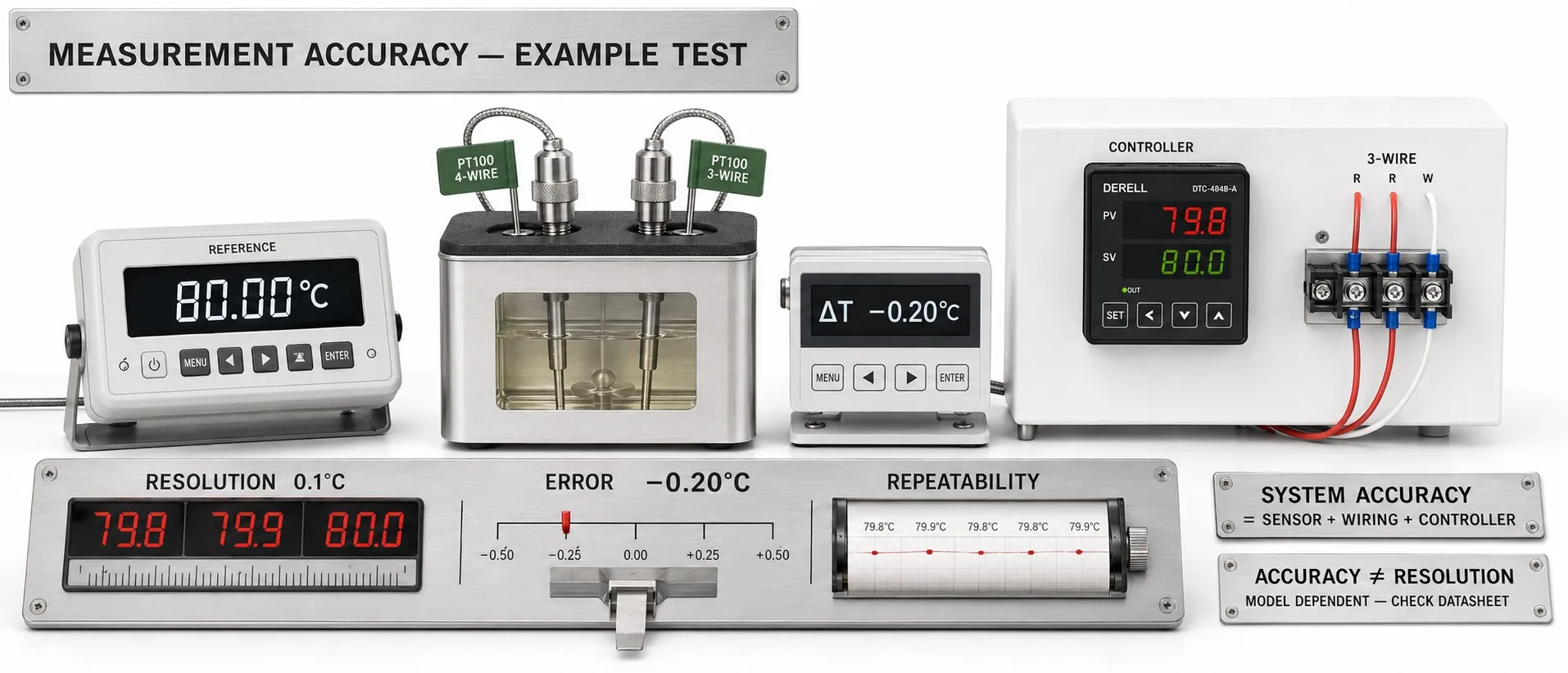
Decimal places on the display do not establish accuracy
Hello, a temperature controller's measurement accuracy concerns how closely its indicated temperature agrees with a reference temperature. A published error limit applies to specified input types, ranges and ambient conditions. Without the model details, no single figure such as “±0.5 °C” can be assigned to every controller.
Accuracy, resolution and repeatability are different
Resolution is the smallest distinguishable display increment. A display showing 100.0 °C and changing in 0.1 °C steps does not prove an accuracy of ±0.1 °C. ADC bit depth alone does not establish the accuracy of the complete temperature measurement.
Repeatability describes agreement between repeated measurements under the same conditions. A controller can consistently show similar values while reading systematically high. Do not confuse a stable indication with a correct indication.
Editor's note: A steady reading of 102.0 °C in an environment actually at 100 °C illustrates how good repeatability can coexist with measurement error. Adding more decimal places does not remove that error.
How should percentage and digit specifications be read?
For example, ±0.3% of reading at 200 °C gives ±0.6 °C. In contrast, for a 0–1000 °C range, ±0.3% of full scale gives ±3 °C if full scale is defined as 1000 °C. Reading and full scale are different bases for calculation; check the manual's FS definition and the applicable range settings.
±1 digit generally means one count of the least significant displayed digit. With a 0.1 °C increment, 1 digit equals 0.1 °C. A hypothetical specification of ±(0.3% of reading + 1 digit) gives ±0.7 °C at 200.0 °C. Any additional condition, such as “or ±1 °C, whichever is greater”, must also be applied. This example is not a specification for a particular product.
Controller error is different from total system error
The controller's electronic input accuracy does not automatically include the external sensor's tolerance. Sensor compatibility, sensor class, wiring and installation must be assessed separately. Read whether the published figure includes sensor tolerance and compensation errors; avoid counting an effect twice if it is already included in a total specification.
Lead resistance matters in Pt100 measurements. In a two-wire connection, lead resistance can add to the measured resistance. Three-wire compensation depends on resistance matching and the input circuit; four-wire measurement can greatly reduce lead-resistance effects. Not every controller supports all connection types.
For thermocouples, check the correct type, polarity, suitable extension or compensating cable and cold-junction compensation. Temperature changes at the terminal area can also affect the result. Do not conceal an installation or wiring error using only a display offset.
An accurate sensor can still measure the wrong location
Insufficient immersion, poor surface contact or a sensor positioned too close to the heater can create a difference between the indicated value and the target product temperature. The sensor location and the critical point in the product may not be at the same temperature. Thermal response lag also matters during rapid changes.
Assess the controller's ambient temperature, electromagnetic interference and input filters as well. More filtering can reduce fluctuations, but does not correct systematic error and can slow the response. Include any specified additional temperature effects outside the reference conditions.
Calibration and adjustment are different operations
Calibration establishes a relationship between reference values and instrument indications under specified conditions, taking measurement uncertainties into account. Adjustment changes the instrument's indication. Entering an offset in a menu is not, by itself, calibration. Check the result again after an adjustment.
Testing the controller input with an electrical simulator does not test the entire sensor and installation. To assess the complete measurement chain, compare the sensor, connections and indicator together against a suitable reference, with adequate temperature stability and appropriate points across the working range. Include reference uncertainty and temperature distribution in the evaluation.
Reliable measurement is the foundation of stable control
Good PID control and suitable control loop settings cannot make an incorrect measurement accurate. A controller can hold the wrong temperature very steadily. Set maintenance and verification intervals according to operating conditions, required tolerances and previous drift; investigate sensor and wiring faults when deviations recur.
When selecting a controller, first establish the required process tolerance. Then assess the sensor, electronic input, wiring and installation together. For a product requirement of ±1 °C, a controller specification of ±1 °C alone does not prove that the whole system meets the requirement.
Temperature controllers | Temperature controller FAQ | Temperature controller prices