
What is the installation process of the device?
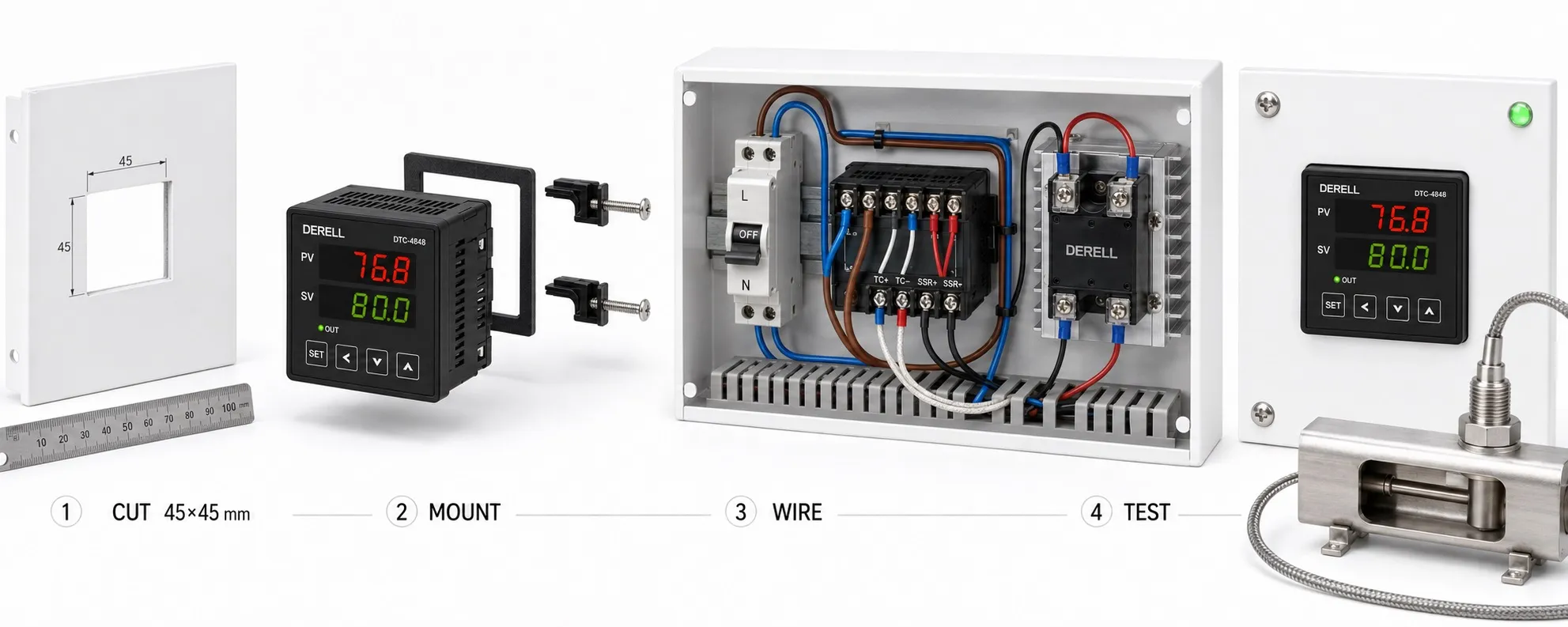
From mechanical mounting to a controlled first start
Hello everyone. Installing a temperature controller involves mounting the instrument, connecting the measurement chain, preparing the power circuit and verifying control behaviour. A connection that looks secure can still perform the wrong function. An incorrect input type, output selection or control direction can cause unexpected operation. Use the exact model's wiring diagram and the site's electrical drawings throughout the installation.
Identify the complete model and its options
Controllers with identical front panels can have different supplies, outputs and communication options. Match the full nameplate code to the manual; identify the AC/DC supply and voltage range, sensor input, control output and alarm contacts. Controller selection comes before terminal assignments. Moving wires to the same terminal numbers on a replacement instrument does not establish equivalent connections.
The external load circuit can remain live while the controller is in STOP. Qualified personnel should identify and isolate the controller supply, heater circuit and separately powered alarm circuits, prevent reconnection and verify that they are de-energised. Observe the manufacturer's discharge waiting time. A low-level measurement signal does not guarantee that the connected sensor is always at a safe electrical potential.
Use the panel cutout drawing
The front-frame dimensions differ from the required panel opening. For example, the Autonics TK4S manual specifies a 45 mm cutout in both directions, with a +0.6/0 mm tolerance. This is a model-specific example: use your instrument's specified cutout, panel thickness, rear clearance and spacing. Fit the gasket and brackets in the stated order without distorting the housing or seal. DIN rail mounting requires a controller or adapter designed for that arrangement.
Assess temperature and humidity at the controller's actual location inside the cabinet. SSR heat sinks and power supplies can create local hot spots. The IP rating also depends on installation: fitting a gasket to an OMRON E5CC-U does not provide the protection available with the specified gasket on an E5CC/E5CC-B. Front-panel protection should not be assumed to extend to rear terminals.
Plan supply wiring and cable routes together
Provide supply connections, isolation and overcurrent protection according to the electrical design. Follow the model instructions for conductor size, stripping length and terminal torque. Route sensor and communication cables separately from motor, drive-output, contactor and heater power wiring. Screen connections and equipotential bonding must follow the equipment manuals and the site's EMC design. “Always ground the screen at one end” is not a universal rule for every connection.
Match the sensor type, wiring and position
Check the supported sensor types first. A Type K thermocouple requires the appropriate Type K input configuration. Maintain thermocouple polarity and use suitable extension or compensating cable. Colour alone is insufficient evidence because colour standards differ. Avoid arrangements that heat or cool one side of the terminal region used for cold-junction compensation.
Pt100 wiring differs between two-, three- and four-wire arrangements. Two-wire lead resistance adds to the measurement; three-wire compensation depends on similar lead resistances. Do not connect every lead of a four-wire probe arbitrarily to an instrument that lacks a four-wire input. Determine the supported arrangement from the model diagram. The probe and cable temperature ratings matter as well as the sensor designation.
Position the probe so it represents the temperature being controlled. Measuring only the heater surface may not indicate product core temperature. Select immersion, contact, protection tubes and sealing according to the sensor instructions. Compare the indication with a suitable reference during commissioning; a measurement accuracy check should not become an exercise in hiding incorrect wiring with an offset.
Commission the scaling of an analogue input
For a 4–20 mA transmitter, verify active/passive input arrangements, loop supply, polarity and load requirements. The manual determines whether an external resistor is needed. For example, 12 mA from a transmitter scaled for 0–400 °C represents 200 °C. If the controller is scaled for 0–200 °C, it will display 100 °C instead. Input scaling and setpoint limits are different settings; check both.
Editor's note: A “4–20 mA” label does not establish that a terminal is a temperature input. The same signal format can serve as a measurement input, a control output or a retransmission output to another system. Confirm its function from the wiring diagram. Applying power to an output mistaken for an input can damage the instrument.
Separate the control output from the load power circuit
A volt-free relay contact does not generate load voltage: it switches an appropriately supplied external circuit. Check contact ratings, load type and contactor coil requirements together. Select inductive-load suppression according to the coil and controller manufacturers' guidance. An SSR drive output connects to the SSR's command input, rather than supplying heater power. Drive voltage, current and polarity must match the SSR input.
Separately select the SSR power circuit for load voltage, current, AC/DC operation, heat sinking and protection. Phase-angle control requires both controller and SSR to support that method. An analogue control output connects to a compatible power controller or actuator. Set the output cycle time to suit the switching device; do not simply transfer a short SSR cycle setting to a mechanical relay.
Use two stages for the first start
Where the manufacturer's procedure permits it, first verify the indication and settings while preventing the load from being energised. Check input type, °C/°F units, control method, heating/cooling assignment, setpoint limits and output functions. In a controlled heating test, rising temperature should act in the direction of reducing heating demand. Confirm the model's definition and actual response rather than relying on the words “direct” or “reverse” alone.
After verifying protective functions, energise the load under controlled conditions. Use a small, safe target change and observe sensor indication, output command and actual load current together. An OUT indicator does not prove that heater current is flowing. With PID temperature control, establish correct wiring and functions before tuning the loop.
Test the response beyond the alarm display
An absolute high-temperature alarm differs from a deviation alarm referenced to the setpoint. Verify alarm type, hysteresis, delay, latching and relay assignment. Use an approved procedure to test sensor-fault output behaviour, the alarm contact and, where fitted, the independent limiter's ability to disconnect the load. Do not assume every model gives zero output when a sensor error code appears. Include the specified behaviour during power loss and restoration in the test scope.
Finish communications and PID setup
For RS-485/Modbus, confirm the port option, bus arrangement, common reference and termination using the applicable manuals. Do not assume A/B labels mean the same thing across manufacturers. Match address, baud rate, parity, registers and data scaling. Verify reading first; enable remote setpoint writes after establishing local limits and the response to communication loss.
Evaluate PID gains or auto-tuning under a representative load and within permitted temperature limits. Auto-tuning can make the process oscillate. Sensor response time, product heating time and output cycle time are different quantities. Complete the installation by recording a parameter backup, current drawings, test results and a maintenance plan.
Related installation and control guides
Products and sensors: Temperature controllers, temperature controller prices and temperature sensors.
Commissioning checks: process delay and system dynamics, common PID problems and power consumption and energy efficiency.
Safety and further questions: EN 61010 electrical safety scope and temperature controller questions and answers.
Sources
Autonics TK user manual: panel cutouts, wiring and output settings
Eurotherm 3200 engineering manual: installation, wiring and configuration; HA028651 Issue 7
OMRON E5CC family: mounting accessories and gasket requirements
OMRON: supply, wiring, environmental and safe-use precautions
WIKA: two-, three- and four-wire Pt100 connections
Modbus Organization: serial line implementation guide, V1.02
Beamex: sensor immersion, stabilisation and temperature checks