
What are the maintenance requirements of the device?
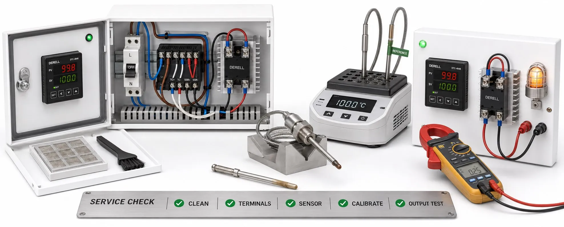
Keep measurement and control performance reliable
Hello everyone. Maintaining a temperature controller involves more than checking whether the displayed value looks reasonable. The sensor, field wiring, controller, power switching device and alarm chain need to be considered together. A controller can display the correct temperature while a failed SSR keeps the heater energised; a healthy sensor cannot prevent problems caused by incorrect settings. A useful maintenance plan therefore checks measurement accuracy, control behaviour and protective functions separately.
Set intervals around operating conditions and evidence
There is no universal requirement to calibrate every controller every six months. Choose intervals using manufacturer guidance, duty, drift history, environment and the consequences of error, together with applicable sector requirements. ILAC-G24/OIML D 10 recommends reviewing intervals using results. A process with tight tolerances may need more frequent intermediate checks than an occasionally used general-purpose heater.
A practical plan combines operator observations, physical inspections during planned shutdowns, scheduled measurement checks and recommissioning after changes. Sensor replacement, cabinet washdown, an overtemperature event or unexplained drift can justify an investigation before the next scheduled date. Record unexpected temperature behaviour as well as visible instrument faults.
Record the condition and prepare for intervention
First record the model, serial number, current settings, alarm history and load conditions associated with the problem. Qualified personnel should then prepare the work using the relevant installation and wiring arrangements. Selecting STOP does not provide electrical isolation. Identify the controller supply, external heater supply and separately powered alarm circuits; isolate them, prevent reconnection and verify that they are de-energised. Allow hot surfaces to cool and follow the manual's discharge waiting time.
Distinguish calibration, verification and adjustment
Calibration establishes the relationship between indication and a traceable reference, including uncertainty. Verification checks compliance with specified acceptance requirements. Adjustment changes the indication and normally requires subsequent recalibration. Checking measurement accuracy does not mean altering factory calibration at every service. PID auto-tuning adjusts control behaviour; it does not calibrate the temperature measurement.
For an electrical input check, disconnect the sensor and apply known signals using an appropriate simulator. Thermocouple inputs require suitable leads and cold-junction compensation; RTD inputs require the correct resistance and wiring arrangement. Record the injection point: a signal applied directly at the controller terminals excludes the field sensor and does not test all intervening wiring. Confirm sensor/input compatibility first.
For a sensor check, compare the sensing element with a traceable reference in a suitable bath or dry block. Immersion, thermal contact and stabilisation affect the result. A measurement-chain check assesses the sensor, connections and display within a defined scope. A dry block's setpoint alone is not an error-free reference; the uncertainty of the actual arrangement must be understood.
For example, a procedure for a process operating from 80 to 180 °C might select 80, 130 and 180 °C as test points. These are illustrative, rather than universally required points. If the reference reads 130.0 °C and the controller displays 132.4 °C, the indication error is +2.4 °C. Apply the agreed tolerance and uncertainty-based acceptance method. Entering a −2.4 °C offset at one point does not prove that the entire range is correct. Record as-found and as-left results separately, and recheck scaling and setpoint limits.
Editor's note: A difference between the displayed temperature and the product temperature does not automatically indicate calibration drift. Probe position, surface contact, product core temperature and time to thermal equilibrium can all matter. Compare the same physical location under stable conditions first. Using an offset to hide the wrong sensor type or poor contact can create larger errors elsewhere in the range.
Inspect more than sensor continuity
Look for sheath corrosion, crushing, loose fittings, moisture ingress and movement away from the intended measuring point. With Pt100 wiring, two-wire lead resistance contributes to the reading, while three-wire compensation depends on similar lead resistances. A four-wire sensor must also be connected in an arrangement the controller supports. Use the correct thermocouple extension type and polarity. When replacing a damaged probe, match its sheath material, length, connection and temperature rating as well as its sensor designation.
Separate controller cleaning from cabinet maintenance
Use only the cloth and cleaning agent permitted by the model's manual, and avoid spraying liquid into openings or terminals. Opening the instrument and brushing its circuit board is not a general maintenance procedure. For example, the Eurotherm 3200 manual states that it has no user-serviceable parts. Internal work belongs under the relevant service procedure. Maintain cabinet filters and fans according to their own instructions, and monitor temperature and humidity around the controller. A front-panel IP rating does not automatically provide equivalent protection at the rear terminals.
Check relays, SSRs and the load circuit
Investigate terminal discolouration, melting or damage, along with blocked heat sinks and faulty cooling fans. Avoid indiscriminate retightening; use the torque specified for the actual terminal. Mechanical relay life depends on the load and number of switching operations. An unnecessarily short output cycle time can accelerate contact wear; an SSR cycle setting should not simply be transferred to a mechanical relay.
An SSR has no moving contacts, but still needs effective heat dissipation and checks of actual load current. An extinguished output indicator does not prove that power to the load has been removed. Separately test the arrangement intended to disconnect the load after an SSR fault. If temperature continues to rise, investigate the power switching chain first; changing the control algorithm is not a repair for a failed power device.
Test the complete response to faults
A planned, controlled test should verify the high-temperature alarm, alarm relay, configured output response to a sensor fault and, where fitted, the independent limiter's ability to disconnect the load. The model manual and the site's approved test procedure define the expected response. Disconnecting sensor wires casually during production is not an appropriate test. Clearing an error code does not demonstrate that its cause has been removed.
Compare the local indication with PLC/HMI records. For industrial communications, check scaling, units, addresses and data types; test the specified response to communication loss. If overshoot or cycling appears during restart, examine sensor installation, load changes and common PID problems. Process delay and sensor response time are different from display refresh rate.
Control backups, updates and replacements
Back up parameters if the instrument supports it; otherwise use a settings record. Preserve input type, units, offsets, output assignments, PID values, alarm limits, fault output behaviour and communication settings together. Not every controller supports field firmware updates. Consider an update only for a compatible model and version, using the manufacturer's stated purpose and procedure; it is not a compulsory maintenance step. For replacement, controller selection must match supply, inputs, outputs and option codes as well as front-panel size.
Close the service job with usable evidence
The record should identify the instrument, date, test scope, reference equipment, results, uncertainty and acceptance method, replaced parts and final configuration version. If a measurement is outside tolerance, assess the possible impact on earlier production. Repeated resets, liquid ingress, burn marks or failed verification call for a service investigation. Before returning to production, remove temporary test connections, restore protective functions and confirm operation by observing temperature trends under a representative load.
Related technical guides
Products and scope: Temperature controllers, temperature controller prices and temperature sensors.
Checks after maintenance: PID gain adjustment, using PID for temperature control and power consumption and energy efficiency.
Further guidance: maximum temperature capability and temperature controller questions and answers.
Sources
ILAC-G24/OIML D 10:2022: determining recalibration intervals
BIPM/JCGM VIM: definition of calibration and distinction from adjustment
Beamex: how to calibrate temperature sensors
Fluke: dry-block and liquid-bath temperature calibration
WIKA: two-, three- and four-wire Pt100 connections
Eurotherm 3200 engineering manual: service, cleaning and input checks; HA028651, Issue 7
OMRON: temperature controller wiring, relay life and operating precautions