
ATV 56 fault codes
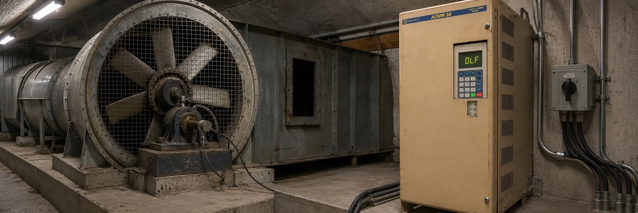
Preventive Maintenance
Before performing preventive maintenance, ensure that all power is removed and check the bus voltage. Regular preventive maintenance should include:
- Checking Connections: Inspect the condition and tightness of all connections.
- Ventilation: Ensure that the ventilation is effective and that the temperature around the drive controller remains at an acceptable level.
- Cleaning: Remove dust and debris from the drive controller as necessary.
- Troubleshooting: If anything unusual occurs when putting the drive controller into service or during operation, make sure all recommendations relating to the environment, mounting, and connecting the drive controller have been followed.
LED Indicators
The LEDs on the front of the drive controller provide important status information:
- FAULT (Red): Illuminated when a fault exists.
- CAUTION (Yellow):
- Illuminated with Fault LED OFF: Drive controller is running and in current limit. The LED may appear to flash rapidly as the drive controller regulates at the current limit.
- Slow Flashing with Fault LED OFF: This Pre-Alarm indicates either a Drive Overtemperature Fault or a Motor Overload Fault. Consult the Keypad Display for Motor Thermal State or Drive Thermal State to determine which condition is causing the Pre-Alarm. If either of these thermal states exceeds 100%, the Caution LED will flash slowly.
- Illuminated with Fault LED ON: A drive controller fault exists on either Motor Overload or Drive Overtemperature, and the cool-down period has not yet expired. Consult the fault display on the keypad or the fault history in Menu 3 to determine the most recent fault.
- POWER (Green): Illuminated when the drive controller is powered; DC bus ≥ 50 V or voltage is present at CL1-CL2.
- DC BUS (Red): Illuminated when the DC bus ≥ 50 V.
The ALTIVAR 56 drive controller can store up to eight faults and display them as messages on the keypad display. These fault messages allow access to Fault History Screens, which display the drive controller run status at the time of each fault. For more information on Fault History Screens, see the relevant chapter in the manual.
Display off or partial display
- Probable Causes:
- No control supply: The drive controller is not receiving the necessary control voltage.
- Control voltage too low: The voltage supplied to the control circuit is insufficient.
- Troubleshooting Procedure:
- Check input line voltage: Refer to Procedure 2 on page 43 of the manual to ensure the input voltage is within the specified range.
- Check fuses and circuit breaker: Refer to Procedure 3 on page 43 to verify that the fuses and circuit breakers are functioning correctly.
- Check CL1-CL2 control terminal connections: Ensure that the connections at the control terminals are secure and properly wired.
IN-PHASE LOSS (Input phase loss)
- Probable Causes:
- No supply to terminals L1-L2-L3: One or more phases of the input power supply are missing.
- Power fuses blown: The fuses protecting the power circuit have failed.
- Brief input line failure (t ≥ 200 ms): There was a temporary interruption in the power supply.
- Troubleshooting Procedure:
- Check input line voltage: Ensure that all three phases are present and the voltage is within the specified range.
- Check fuses and circuit breaker: Verify that the fuses and circuit breakers are intact and functional.
- Reset drive controller: Follow the procedure to reset the drive controller and clear the fault.
- Check connections: Inspect the internal connections for any loose or damaged wires.
UNDERVOLTAGE [1]
- Probable Causes:
- Supply too low: The input voltage is below the minimum threshold for the drive controller.
- Troubleshooting Procedure:
- Check input line voltage: Verify that the input voltage is within the acceptable range for the drive controller model.
- Check Nominal Motor Voltage parameter: Ensure that the motor voltage parameter is set correctly in the drive settings.
- Reset drive controller: Clear the fault by resetting the drive controller.
- Check connections: Inspect the internal connections for any issues.
AC-LIN. OVERVOL [1] (AC Line Overvoltage)
- Probable Causes:
- Supply too high: The input voltage exceeds the maximum threshold for the drive controller.
- Troubleshooting Procedure:
- Check input line voltage: Ensure that the input voltage is not exceeding the specified limit for the drive model.
- Check Nominal Motor Voltage parameter: Verify that the motor voltage setting is appropriate for the application.
DC-BUS OVERVOL [1] (DC Bus Overvoltage)
- Probable Causes:
- Overvoltage or overcurrent due to excessive braking or an overhauling load: The drive is experiencing high voltage or current levels, possibly due to rapid deceleration or a load that is driving the motor.
- Troubleshooting Procedure:
- Increase deceleration time: Adjust the deceleration settings to reduce the rate of deceleration, which can help manage the voltage levels.
- Add braking option if necessary: Consider installing a braking resistor or other braking options to dissipate excess energy.
- Reset is possible if line voltage ≤ 550 V: If the line voltage is within the acceptable range, reset the drive controller to clear the fault.
OVERTEMP DRIVE (Drive Overtemp.)
- Probable Causes:
- Heat sink temperature too high (≥ 203 °F / 95 °C): The temperature of the drive's heat sink has exceeded the safe operating limit.
- Troubleshooting Procedure:
- Check motor load, fan, and ambient temperature around the drive controller: Ensure that the motor is not overloaded, the cooling fan is functioning, and the ambient temperature is within the acceptable range.
- Wait for the drive controller to cool down before resetting: Allow the drive to cool before attempting to reset and clear the fault.
MOT. OVERLOAD (Motor Overload)
- Probable Causes:
- Thermal trip setting is ≥ 118% of normal thermal state (109% of nominal current): The motor has experienced a prolonged overload or an output phase failure.
- Motor power rating too low for application: The motor is not adequately sized for the demands of the application.
- Troubleshooting Procedure:
- Check the setting of the MOT. OVERLOAD parameter: Compare the setting with the motor's rated current to ensure it is appropriate.
- Check the load and compare with operating speed: Ensure that the motor is not being overloaded relative to its speed.
- Check braking conditions: Investigate if there is a possibility of single-phase operation or other braking issues.
- Wait approximately 7 minutes before resetting: Allow time for the motor to cool down before attempting to reset the drive.
- Verify motor and drive controller selection: Ensure that the motor and drive are correctly sized for the application.
- For motors with continuous current rating less than 50% of the drive controller current rating: Refer to Chapter 5 for additional guidance.
SHORT CIRCUIT [1]
Causes:
- Desaturation: A short circuit or grounding on the drive controller output.
- LIC exceeded: Internal drive fault or motor improperly applied.
Troubleshooting:
- Desaturation: Disconnect power, check connecting cables and motor insulation.
- Internal drive fault: Use drive controller self-diagnostics (refer to Chapter 5).
- Motor improperly applied: Review "MOTOR CONSIDERATIONS" (page 39).
PRECHARGE FAIL [2]
Cause: Fault in the capacitor charge relay control.
Troubleshooting:
- Check connections in the drive controller following the Bus Voltage Measurement Procedure (page 42).
INTERNAL FAULT [1]
Causes:
- Internal connection fault.
- Missing connections on CL1 and CL2.
Troubleshooting:
- Check internal connections following the Bus Voltage Measurement procedure (page 42).
LOSS FOLLOWER
Cause: Loss of 4-20 mA signal on AI2 input.
Troubleshooting:
- Verify signal connections.
- Check the signal.