
Teco S310 fault codes
TECO S310 Fault Codes and Troubleshooting
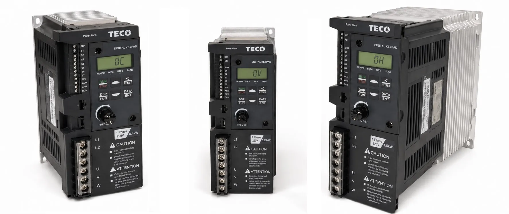
Below are the most common TECO S310 fault codes, stop messages and alarm conditions, together with the checks normally made before the drive is removed for service. Before troubleshooting, check the incoming supply, motor wiring, grounding and mechanical load.
Err1 – Keypad Operation Error
Possible causes:
- The ▲ or ▼ key was pressed while the drive was running with a preset frequency source (00-05 > 0).
- A parameter that cannot be changed while running was edited.
Check: The ▲ and ▼ keys can be used for frequency adjustment only when 00-05 = 0. Parameters that are locked during operation should be changed with the drive in STOP mode.
Err2 – Parameter Setting Error
Cause: The entered value is outside the permitted parameter range.
Check: Enter a value within the allowable range for that parameter.
Err5 – Parameter Cannot Be Changed During Communication
Possible causes:
- A control command is being sent during communication.
- Parameters 08-02 to 08-05 are being changed while communication is active.
Check: Set parameters 08-02 to 08-05 before starting communication and make sure the required enable command has been issued.
Err6 – Communication Error
Possible causes:
- Communication wiring problem.
- Incorrect communication parameters.
- Checksum error.
Check: Inspect the communication wiring and hardware, then verify parameters 08-02 to 08-05.
Err7 – Parameter Conflict
Possible causes:
- Conflict while changing functions 12-00 / 12-06.
- Abnormal voltage or current detection circuit.
Check: If the fault cannot be reset after the parameter settings have been checked, the drive may require service inspection.
S310 Alarm LED Behaviour
Non-resettable faults such as CTER, EPR, OH, LV, OV and OC normally cause the Alarm LED to flash quickly. Switch the drive off and power it up again after the fault condition has been checked. If the same alarm returns immediately, the drive may need service.
Resettable faults such as OH-C, OV-C, OC-S, OC-D, OC-C, OC-A, OL2 and OL1 normally cause the Alarm LED to flash more slowly. Remove the cause of the fault, then cycle the drive power if required.
OC – Overcurrent While Stopped
Possible causes:
- Current detection circuit fault.
- Poor connection in the CT (current transformer) signal circuit.
Check: Inspect the motor and power wiring for electrical noise or connection problems. If the fault remains with the motor disconnected and the supply is normal, the drive should be inspected by service personnel.
OL1 – Motor Overload
Possible causes:
- Motor load is too high.
- Parameter 07-05 does not match the motor data.
Check: Check the mechanical load and set parameter 07-05 according to the motor nameplate data. Make sure the motor is correctly sized for the application.
OL2 – Inverter Overload
Cause: The load is above the continuous capacity of the drive.
Check: Reduce the load or use a drive with a suitable current and overload rating for the application.
LV-C (Lu-c) – Low Voltage During Operation
Possible causes:
- Incoming supply voltage is too low.
- Supply voltage is unstable or fluctuating.
Check:
- Measure the incoming supply voltage under load.
- Check parameter 4-04 where applicable.
- Increase the acceleration time if the DC bus drops heavily during starting.
- An input reactor may help where the incoming supply is unstable.
- Check that the motor and drive are correctly sized for the load.
Stp0 – Zero Speed at Stop
This message can appear when the frequency reference is below 0.1 Hz. If zero speed is intentional, no action is normally required. Otherwise, check the frequency reference and minimum frequency settings.
Stp1 – Direct Start at Power-up Not Allowed
The drive is set for external terminal control (00-03 = 1) while direct start at power-up is disabled (04-09 = 1).
Check: If automatic start after power-up is required by the application, check 04-09 and the state of the RUN input. Use this function only where an automatic restart is safe for the machine.
Stp2 – Keypad STOP Used in External Control Mode
The keypad STOP key has been used while the drive is running in external terminal control mode (00-03 = 1).
Check: Release and reapply the external RUN command. Also check parameters 04-01 and 00-03.
E.S. – External Rapid Stop
The drive decelerates to a stop when the external rapid-stop function is activated through a multifunction input.
Check: Check multifunction input parameters 01-00 to 01-04 and confirm that the external rapid-stop signal is operating as intended.
b.b – External Base Block
The inverter output is disabled when the external Base Block input becomes active. The motor will normally coast rather than follow a controlled deceleration ramp.
Check: Check parameters 01-00 to 01-04 and the external Base Block input circuit.
OC-S – Overcurrent at Start
Possible causes:
- Short circuit between the motor winding and frame.
- Ground fault in the motor or motor cable.
- Fault in the IGBT power stage.
Check: Inspect the motor and motor cable for short circuits and insulation faults. If the motor and wiring test correctly, the drive power stage may require service inspection.
OC-D – Overcurrent During Deceleration
Cause: The deceleration time is too short for the load.
Check: Increase the deceleration time.
OC-A – Overcurrent During Acceleration
Possible causes:
- Acceleration time is too short.
- Motor rating is higher than the drive rating.
- Short circuit in the motor windings.
- Ground fault in the motor cable.
- IGBT power stage fault.
Check: Increase the acceleration time, confirm that the motor and drive ratings are suitable for each other, and check the motor and cable insulation.
OC-C – Overcurrent at Constant Speed
Possible causes:
- Sudden load change.
- Sudden supply disturbance.
Check: Look for sudden changes in the mechanical load or incoming supply. If the drive is operating close to its limit, check whether a higher-capacity model is required.
OV-C (ou-c) – Overvoltage During Operation or Deceleration
Possible causes:
- Deceleration time is too short.
- High load inertia.
- Incoming voltage is unstable or too high.
Check:
- Increase the deceleration time.
- Use a braking resistor or braking unit where the application produces significant regenerative energy.
- Check the incoming supply voltage.
- An input reactor may help where the supply is unstable.
- Check that the drive rating is suitable for the application.
OH-C – Heatsink Overtemperature During Operation
Possible causes:
- Heavy or continuous overload.
- High ambient temperature.
- Poor panel ventilation.
Check: Check the mechanical load, cooling fan, air path and panel ventilation. Make sure the drive has enough capacity for the duty cycle.
OV (Ou) – Overvoltage While Stopped
Possible cause: Excessive DC bus voltage while stopped, or a problem in the voltage detection circuit.
Check: Verify the incoming supply voltage. If the supply is normal and the alarm remains, the voltage detection circuit may require service inspection.
LV (Lu) – Low Voltage While Stopped
Possible causes:
- Incoming voltage too low.
- Pre-charge resistor or fuse problem.
- Voltage detection circuit fault.
Check: Measure the supply voltage and inspect the pre-charge circuit. If the supply is correct and the alarm remains, the drive should be checked by qualified service personnel.
OH – Overtemperature While Stopped
Possible causes:
- Temperature detection circuit fault.
- High ambient temperature or poor ventilation.
Check: Check the ambient temperature and cooling conditions. If these are normal, the temperature detection circuit may require inspection.
CTER – Current Sensor Detection Error
Cause: Fault in the current sensor or its detection circuit.
Check: This normally requires inspection of the drive's current measurement circuit.
EPR – EEPROM Error
Cause: EEPROM memory or related control circuit fault.
Check: If the error cannot be cleared by a normal power cycle, the control board should be inspected by service personnel.
COT – Communication Error
Cause: A communication fault has been detected.
Check: Check the communication wiring, communication settings and the parameters in Group 8.
Related TECO S310 Pages