
Teco N3 fault codes
TECO N3 Fault Codes and Troubleshooting
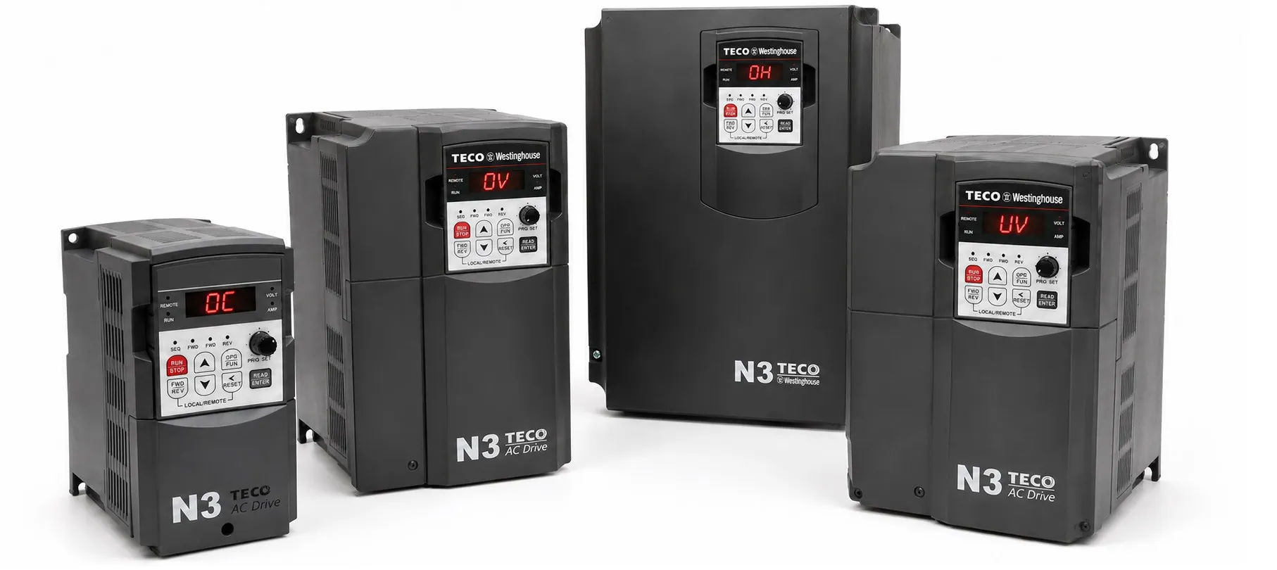
Below are common TECO N3 inverter faults, stop messages and basic troubleshooting checks. Before working through a fault code, check the incoming supply, motor wiring, grounding, mechanical load and run command.
Basic Operating Problems
Motor Will Not Run
- Check for supply voltage at L1(L), L2 and L3(N) on three-phase units, or L1(L) and L3(N) on single-phase units.
- Make sure the input voltage is correct and the terminal screws are tight.
- Check for output voltage at T1, T2 and T3.
- Make sure the motor or machine is not mechanically jammed or heavily overloaded.
- Check the motor and control wiring.
- Confirm that a Forward or Reverse RUN command is present and that the correct control mode has been selected. If necessary, try running the drive from the keypad.
Motor Runs in the Wrong Direction
- Check that T1, T2 and T3 are connected correctly to the motor U, V and W terminals.
- Check the Forward / Reverse input wiring.
Motor Speed Cannot Be Adjusted
- If an analog frequency reference is being used, check the signal wiring.
- Check the selected run mode and frequency command source.
- Try controlling the drive from the keypad to narrow down the problem.
- Make sure the mechanical load is not excessive.
Motor Speed Is Too High or Too Low
- Check the motor data, including pole count and rated voltage.
- Check the machine gear ratio.
- Verify the maximum output frequency setting.
Motor Speed Changes Erratically
- Reduce the load if it is too high.
- Check for sudden changes in the mechanical load.
- Make sure the motor and inverter are correctly sized for the application.
- Check the incoming supply for voltage fluctuations or phase loss.
- An AC input reactor may help on unstable supplies. On three-phase systems, also check the phase wiring.
TECO N3 Alarm and Fault Codes
CPF – Program / Control Error
The drive has detected a program or control circuit problem. External electrical noise or EMI is listed as one possible cause.
Check: Look for interference from contactors, relays and other inductive loads. Where required, an appropriate RC suppressor can be fitted across the contactor coil.
EPR – EEPROM Error
A problem has been detected in the EEPROM memory or its control circuit.
Check: If the fault cannot be cleared by a normal power cycle, the EEPROM or control board may need inspection.
*-OV- – Overvoltage While Stopped
The drive detects excessive voltage while stopped. A fault in the voltage detection circuit is one possible cause.
Check: Measure the incoming supply voltage. If the supply is normal and the alarm remains, the voltage detection circuit should be checked.
*-LV- – Undervoltage While Stopped
Possible causes:
- Input voltage too low.
- Failed pre-charge / power resistor.
- Blown fuse.
- Voltage detection circuit fault.
Check: Verify the incoming voltage, fuse and pre-charge circuit.
*-OH- – Overtemperature While Stopped
An overtemperature condition is being detected while the drive is stopped. This may be caused by poor ventilation or a temperature detection circuit problem.
Check: Check ambient temperature and panel ventilation. If cooling conditions are normal, the temperature detection circuit may need inspection.
CTER – Current Transducer Detection Error
A problem has been detected in the current sensor or current measurement circuit.
Check: The drive's current measurement circuit should be inspected.
OC-S – Overcurrent at Start
Possible causes:
- Short circuit between the motor winding and frame.
- Ground fault in the motor or motor cable.
- Fault in the inverter power module.
Check: Test the motor insulation and motor wiring. If the motor and cable are good, the inverter power stage may need inspection.
OC-D – Overcurrent During Deceleration
Cause: The deceleration time is too short for the load.
Check: Increase the deceleration time with parameter b0008.
OC-A – Overcurrent During Acceleration
Possible causes:
- Acceleration time too short.
- Motor rating higher than the inverter rating.
- Short circuit in the motor windings.
- Ground fault in the motor cable.
- IGBT power module fault.
Check: Increase the acceleration time with b0007. Check that the motor and inverter ratings match, and test the motor and cable insulation.
OC-C – Overcurrent During Operation
Overcurrent during normal running can be caused by sudden load changes or disturbances on the incoming supply.
Check: Check the mechanical load and supply. The source documentation also suggests repeating Auto Tuning with A006 = 1 or checking stator resistance parameter A168 where required.
OV-C – Overvoltage During Operation / Deceleration
Possible causes:
- Deceleration time too short.
- High load inertia.
- Unstable incoming voltage.
Check: Increase the deceleration time. If the machine produces significant regenerative energy, use a braking resistor or braking unit. An input reactor may also help where the supply is unstable.
Err4 – CPU Interrupt Error
An unexpected CPU interrupt has been detected. External electrical noise is listed as a possible cause.
Check: Check grounding and separate motor/power cables from control wiring where possible. If the fault repeatedly returns, the control board should be inspected.
OVSP – Motor Overspeed
Possible causes:
- Incorrect motor or load conditions.
- Drive capacity too small for the application.
- Incorrect motor parameters in vector mode.
- Vector control gain too high.
- Current detection circuit fault.
Check: Check acceleration and deceleration parameters b007 / b008 and verify the motor data. The source documentation also refers to stator and rotor resistance gain settings A168 / A169.
OC – Overcurrent While Stopped
The OC detection circuit or CT signal wiring may be faulty.
Check: Check the power and motor wiring. If the fault remains, the current detection circuit should be inspected.
OL1 – Motor Overload
Possible causes:
- Motor undersized for the load.
- Incorrect motor settings in A002 and A119–A122.
Check: Check the mechanical load, motor sizing and related motor parameters.
OL2 – Inverter Overload
The load is above the continuous capacity of the inverter.
Check: Reduce the load or use an inverter with a suitable current and overload rating.
OL3 – Over Torque
The mechanical load may be too high, or parameters A125 and A126 may not be correct for the application.
Check: Check the mechanical load, inverter capacity and A125 / A126 settings.
LVC – Undervoltage During Operation
Possible causes:
- Incoming voltage too low.
- Supply voltage fluctuating.
- Main circuit relay problem.
Check: Check the supply voltage. Increase acceleration time with b0007 if the DC bus drops heavily during starting. An input reactor may help on unstable supplies.
OH-C – Heatsink Overtemperature During Operation
Possible causes:
- Excessive load.
- High ambient temperature.
- Poor ventilation.
Check: Check the mechanical load, inverter sizing, cooling fan and panel ventilation.
STPO – Zero Speed Stop
This message appears when the frequency reference is below 0.1 Hz. If this is not intended, increase the frequency reference.
STP1 – Direct Start at Power-up Disabled
The inverter is in external terminal control and is not allowed to start automatically when power is applied.
Check: If direct start is required by the application, the source documentation specifies A017 = 0001.
STP2 – Keypad STOP Command
STP2 appears when the keypad STOP key is pressed while the inverter is operating in external control or communication mode.
Check: Remove and reapply the RUN command, or send a STOP followed by a RUN command from the PLC or PC.
E.S. – External Emergency Stop
The inverter decelerates to a stop when an external emergency-stop signal is received through a multifunction input.
b.b. – External Base Block
When the external Base Block input becomes active, inverter output is disabled and the motor coasts to a stop. The display then shows b.b.
ATER – Auto-Tuning Error
Auto-tuning may fail if the motor data is incorrect or if the procedure is stopped before it finishes.
Check: Verify the motor nameplate data and repeat the Auto-Tuning procedure.
PDER – PID Feedback Signal Loss
The PID feedback signal or feedback input circuit has been lost.
Check: Check the PID sensor, analog input and feedback wiring.
LOC – Parameter / Reverse Command Lock
This message appears when frequency adjustment or reverse operation is blocked by parameter settings.
Check: According to the source documentation, check A039 = 0000 and b002 = 0000.
Err1 – Keypad Operation Error
This can occur when ▲ / ▼ is used while b004 > 0, or when a parameter that cannot be changed during RUN is edited.
Check: Confirm b004 = 0 where required and change locked parameters only while the drive is stopped.
Err2 – Parameter Setting Error
This fault is related to the permitted relationship between b006 and parameters A032, A033, A034 and A035, or the condition b005 ≤ b006.
Check: Review the related parameter values and set them within the permitted range.
Err5 – Parameter Cannot Be Changed During Communication
This can occur when a locked command is enabled during communication or parameters A164–A167 are changed while communication is active.
Check: Issue the required enable command and set A164–A167 before starting communication.
Err6 – Communication Error
Possible causes:
- Incorrect communication wiring.
- Incorrect communication parameters.
- Checksum or communication verification error.
Check: Check the wiring, communication hardware and parameters A161–A164.
Err7 – Parameter / Detection Circuit Error
This can occur when changing A175 or when the voltage/current detection circuit is not operating correctly.
Check: Reset the inverter. If the fault returns, the detection circuits should be inspected.
EPr1 – Copy Unit / Parameter Set Error
Possible causes:
- Poor connection to the Copy Unit.
- Faulty Copy Unit.
- Different HP ratings between the Copy Unit data and the inverter.
Check: Check A040, the Copy Unit connection and the drive power rating.
EPr2 – Parameters Do Not Match
The copied parameter set does not match the target inverter.
Check: Make sure the source and target drives have compatible voltage and HP ratings.
Related TECO N3 Pages