
Teco L510 fault codes
TECO L510 Fault Codes and Troubleshooting
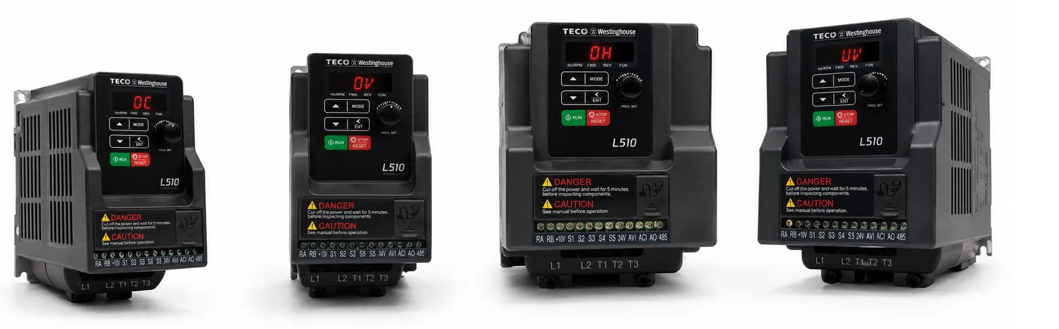
Below are common TECO L510 fault codes, stop messages and basic troubleshooting checks. Before working through a fault, check the incoming supply, motor wiring, grounding, mechanical load and run command.
Basic Operating Problems
Motor Runs in the Wrong Direction
- Check the Forward and Reverse input wiring.
- If an analog frequency reference is being used, check the signal wiring.
- Make sure the correct operating mode has been selected.
Motor Speed Cannot Be Adjusted
- Reduce the mechanical load if it is too high.
- Check the motor data, including pole count and rated voltage.
- Check the machine gear ratio.
Motor Speed Is Too High or Too Low
- Check the maximum output frequency setting.
- Reduce the load if necessary.
- Check for large changes in the mechanical load and make sure the motor and inverter are correctly sized.
- On an unstable single-phase supply, an AC input reactor may help.
Motor Speed Changes Erratically
- Check the incoming supply for voltage fluctuations or phase loss.
- Check that power is connected to the correct L1, L2 and L3 terminals.
- Make sure the input voltage is correct and the power terminals are tight.
- Check the voltage at T1, T2 and T3.
- Check for excessive mechanical load or a stalled motor.
- Confirm that a Forward or Reverse RUN command is present.
- If analog speed control is used, check both the signal voltage and wiring.
Motor Will Not Run
- Check the selected operating mode.
- Try running the drive from the keypad to see whether the problem is in the external control circuit.
TECO L510 Fault Codes
-oV- – Overvoltage While Stopped
Possible cause: Voltage detection circuit fault.
Check: Measure the incoming supply voltage. If the supply is normal and the fault remains, the voltage detection circuit should be inspected.
-LV- – Undervoltage While Stopped
Possible causes:
- Incoming voltage too low.
- Pre-charge resistor or fuse fault.
- Voltage detection circuit fault.
Check: Verify the supply voltage, pre-charge resistor and fuse. If these are normal, the detection circuit may need inspection.
-oH- – Overtemperature While Stopped
Possible causes:
- Temperature detection circuit fault.
- High ambient temperature.
- Poor ventilation.
Check: Check the ambient temperature and panel ventilation. If cooling conditions are normal, inspect the temperature detection circuit.
CtEr – Current Sensor Detection Error
Cause: Current sensor or current measurement circuit fault.
Check: The drive's current sensing circuit should be inspected.
EPr – EEPROM Error
Cause: EEPROM memory or related control circuit fault.
Check: If the fault cannot be cleared with a normal power cycle, the EEPROM or control board may need inspection.
Cot – Communication Error
Cause: Loss of communication or incorrect communication settings.
Check: Check the communication wiring, terminals and related parameters.
Faults During Operation
oC-A – Overcurrent During Acceleration
Possible causes:
- Acceleration time too short.
- Motor rating higher than the inverter rating.
- Short circuit between the motor winding and frame.
- Ground fault in the motor cable.
- IGBT power module fault.
Check: Increase the acceleration time. Check that the motor and inverter ratings match, and test the motor and cable insulation.
oC-C – Overcurrent at Constant Speed
Possible causes:
- Sudden load change.
- Disturbance on the incoming supply.
Check: Check the mechanical load and incoming supply. If the drive is operating close to its limit, check whether a larger inverter is required. An input reactor may help on an unstable supply.
oC-d – Overcurrent During Deceleration
Cause: Deceleration time is too short for the load.
Check: Increase the deceleration time.
oC-S – Overcurrent at Start
Possible causes:
- Short circuit between the motor winding and frame.
- Ground fault in the motor or motor cable.
- IGBT power module fault.
Check: Test the motor and motor cable insulation. If both are good, the inverter power stage may need inspection.
oV-C – Overvoltage During Operation / Deceleration
Possible causes:
- Deceleration time too short.
- High load inertia.
- Unstable incoming voltage.
Check: Increase the deceleration time. If the application produces regenerative energy, use a braking resistor or braking unit. An input reactor may also help where the supply is unstable.
oC – Overcurrent While Stopped
Cause: Current detection circuit fault.
Check: Check the motor and power wiring. If the fault remains, the current sensing circuit should be inspected.
oL1 – Motor Overload
Cause: The mechanical load may be too high for the motor.
Check: Check the mechanical load and motor sizing.
oL2 – Inverter Overload
Cause: The load is above the inverter's continuous capacity.
Check: Reduce the load or use an inverter with a suitable current and overload rating.
LV-C – Undervoltage During Operation
Possible causes:
- Incoming voltage too low.
- Supply voltage fluctuating.
Check: Measure the supply voltage under load. If the supply is unstable, an input reactor may help.
Keypad and Parameter Messages
LoC – Parameter / Direction Lock
This message can appear when parameter editing, motor direction or password protection is locked.
Check: According to the source documentation, check parameters 13-06 and 11-00, or enter the correct password.
Err1 – Keypad Operation Error
This can occur when ▲ / ▼ is used while a preset speed is active, or when a parameter that cannot be changed during RUN is edited.
Check: Stop the drive and, where required, confirm 00-05 / 00-06 = 0.
Err2 – Parameter Setting Error
The entered parameter values do not meet the required relationship. The source documentation refers to 00-13 and the condition 00-12 ≤ 00-13.
Check: Review the related parameters and set them within the permitted range.
Err5 – Parameter Cannot Be Changed During Communication
A parameter change is being attempted while communication is active.
Check: Issue the required enable command before communication and set parameters 09-02 to 09-05 beforehand.
Err6 – Communication Error
Possible causes:
- Incorrect communication wiring.
- Incorrect communication parameters.
- Communication protocol mismatch.
Check: Check the communication hardware, wiring and parameter settings.
Err7 – Parameter Conflict / Detection Circuit Error
This may occur while changing functions 13-00 / 13-08, or if the voltage/current detection circuit is not operating correctly.
Check: Reset the inverter. If the fault returns, the detection circuit should be inspected.
Stop Messages
StP0 – Zero Speed at Stop
This message can appear when the frequency reference is below 0.1 Hz. It does not always indicate an actual fault.
StP1 – Direct Start at Power-up Disabled
This can occur when the inverter is in external terminal control (00-02 / 00-03 = 1) and direct start is disabled (07-04 = 1).
Check: If automatic start is required by the application, check the setting and description of parameter 07-04.
StP2 – Keypad STOP
This message appears when the keypad STOP key is pressed while the inverter is operating in external control mode.
Check: Release and reapply the external RUN command.
E.S. – External Rapid Stop
The inverter decelerates to a stop when an external rapid-stop signal is received through a multifunction input.
b.b. – External Base Block
When the Base Block input becomes active, inverter output is disabled and the motor normally coasts to a stop.
PdEr – PID Feedback Loss
The inverter has detected loss of the PID feedback signal.
Check: Check the feedback sensor, analog input and related wiring.
Related TECO L510 Pages
+ TECO L510 Inverter Main Page