
What is the difference between amperage and voltage?
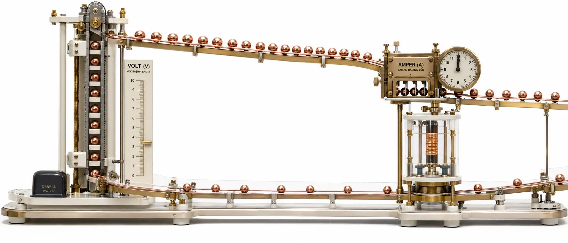
Amps and volts: what each number tells you
Volts describe a difference in electrical potential; amps describe the rate of charge flow. A voltage reading is taken between two points. A current reading belongs to a conductor or circuit branch. The two quantities work together, but neither can be converted into the other without information about the load.
Read the units before interpreting the circuit
The ampere, symbol A, measures electric current. Average current over an interval is I = ΔQ / Δt. 1 A = 1 coulomb per second: one coulomb of net charge passing a cross-section each second. 1000 mA = 1 A, so 250 mA is 0.25 A.
In metals, electrons carry the current; in electrolytes, ions can carry charge too. Conventional current direction follows positive charge flow. Electron drift in a metal is in the opposite direction.
The volt, symbol V, measures potential difference. 1 V = 1 joule per coulomb. A 12 V drop across a resistor means 12 joules of electrical energy are transferred for every coulomb passing through it. Circuit diagrams may use V or U for voltage, but the unit symbol remains V.
Voltage can exist without load current
An open switch can have voltage across its contacts while the ideal open load branch carries no sustained current. An unloaded adapter can similarly show an output voltage. That does not make all currents in the system zero: the adapter may consume power internally, and the voltmeter draws a small current.
Measuring 230 V at an outlet does not establish how many amps an appliance will draw. That depends on the connected load and its operating state. Always identify the voltage reference and the branch whose current is being discussed.
Use resistance to connect voltage and current
For an ohmic resistor at constant temperature, Ohm’s law is V = I × R. To calculate current, rearrange it to I = V / R. At 12 V, a 6 Ω resistor draws 2 A and a 12 Ω resistor draws 1 A. The same voltage can produce different currents in different loads.
Keep the resistance at 6 Ω and raise the voltage from 12 V to 24 V: current rises from 2 A to 4 A. Higher voltage does not universally mean lower current. Lower current follows when comparing suitable DC systems at the same electrical input power: 24 W requires 2 A at 12 V or 1 A at 24 V. Motors and electronic circuits do not always behave like fixed resistors.
A 12 V, 5 A supply does not force 5 A into a device
On a regulated constant-voltage adapter, 12 V specifies output voltage and 5 A its rated current capability under the stated conditions. A device with a current requirement of 1 A normally draws about 1 A; the supply’s higher capacity is not a command to deliver 5 A.
When considering an adapter with a higher current rating, check the required voltage, AC/DC type, polarity, connector and any charging or communication protocol. Extra current capacity cannot correct the wrong voltage. Also remember that current demand can change with motor starting or equipment operating modes.
Watts require both voltage and current
For steady DC, electrical input power is P = V × I. A load taking 2 A at 12 V receives 24 W. This relationship between voltage and watts describes the rate of electrical energy transfer. A voltage or current reading alone is not a power figure.
For single-phase AC, RMS voltage times RMS current gives apparent power: S = Vrms × Irms, in VA. Active power is P = Vrms × Irms × PF. At 230 V, 2 A and true power factor 0.80, the readings correspond to 460 VA and 368 W. The distinction between VA and watts matters when using AC readings.
Keep amps, amp-hours and energy separate
A measures current, Ah measures charge and kWh measures energy. For constant current, amp-hours follow Q = I × t: 2 A for three hours transfers 6 Ah. A device averaging 24 W over those three hours uses 72 Wh, or 0.072 kilowatt-hours. Current, accumulated charge and energy answer different questions.
Measurement connections reflect the difference
Voltage measurement places the instrument in parallel between the two points of interest. Current measurement through a multimeter’s current terminals puts the instrument in series, within its permitted limits. A suitable clamp can measure current around one conductor without opening the circuit; DC measurements require a DC-capable clamp.
Putting current-input probes across a source can create a short circuit. Check the multimeter’s input jacks, function and ratings together. Location matters too: conductor voltage drop can make the reading at the load differ from the reading at the source. Record where the readings were taken and what the equipment was doing at the time.