
What is an ohm? Understanding electrical resistance
What is an ohm? Understanding electrical resistance
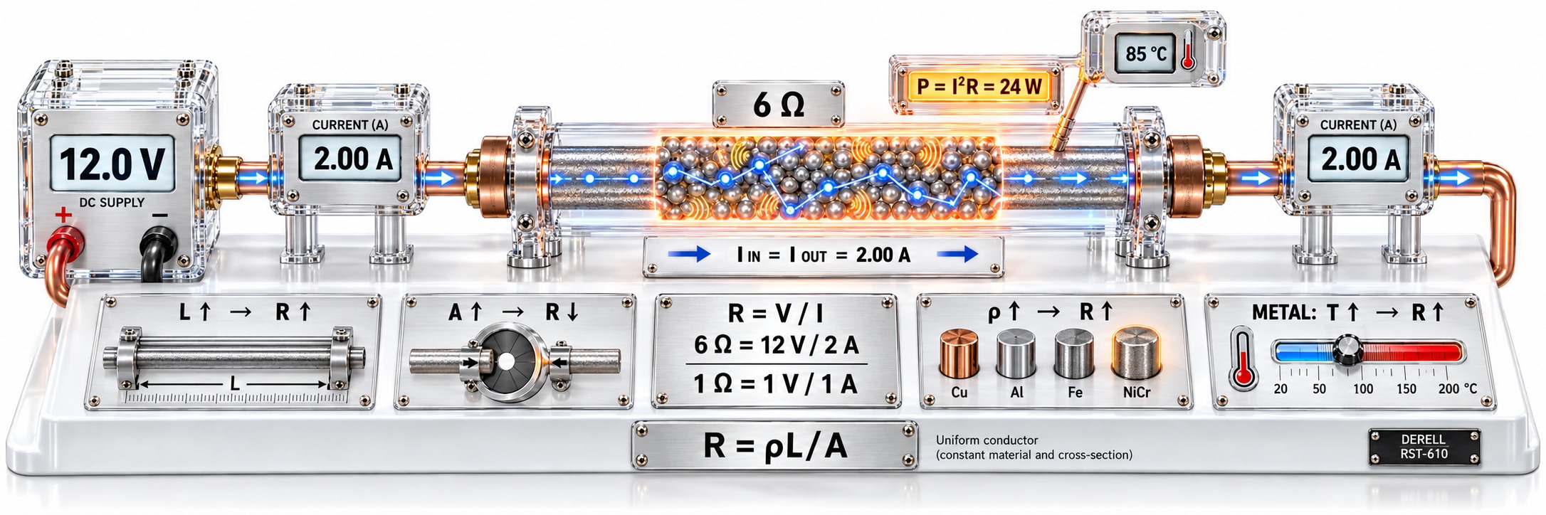
The ohm is the unit of electrical resistance, written Ω. An ohmic element has a resistance of 1 Ω if applying 1 V across it produces a current of 1 A. At the same voltage, increasing resistance reduces current.
Ohms are relevant far beyond the coloured components on a circuit board. Resistance matters when a terminal heats up, a long cable loses voltage, a motor winding is checked, a temperature sensor takes a reading or a drive brakes a motor. The same unit serves different purposes: some applications need very low resistance, while others require a specific value.
Ω, kΩ and MΩ: read the unit first
Resistance is the physical quantity; the ohm is its unit. A component deliberately providing resistance is called a resistor. Cables, windings and contact points have resistance too. For the component itself, see the resistance guide.
4k7 = 4.7 kΩ = 4700 Ω, while 0R22 = 0.22 Ω. Lowercase m and uppercase M mean different things. Ignoring the kΩ or MΩ indicator on a meter can change your interpretation by factors of thousands. For coloured bands, see resistor colour codes.
The same 24 V across three different resistors
Each resistor is considered separately across a 24 V DC source. Values remain constant and the loads are ohmic: I = U / R. Bar lengths are proportional to the calculated currents.
240 Ω
Current: 100 mA
Power dissipated: 2.4 W
1.2 kΩ
Current: 20 mA
Power dissipated: 0.48 W
2.4 kΩ
Current: 10 mA
Power dissipated: 0.24 W
Increasing resistance by a factor of five reduces current to one fifth. Voltage is held constant here. See Ohm’s law for the relationship, and volts, amps and watts for the difference between the electrical quantities.
From circuit boards to machine panels: what does resistance do?
It sets current and signal levels on a board. Resistors limit LED current, divide voltage and prevent inputs from floating. Understanding a component’s role matters as much as reading its value. Why an LED needs a resistor provides an accessible example.
It creates losses in cables. With material, cross-section and temperature unchanged, a longer cable has more resistance. Increasing its cross-section reduces resistance when the other conditions stay the same. A DC circuit calculation must include both outgoing and return paths. This underlies voltage drop in long cables and voltage drop calculations.
It carries measurement information in temperature sensors. A Pt100 temperature sensor element has a nominal resistance of 100 Ω at 0 °C, increasing with temperature. That does not mean it should read 100 Ω at room temperature. NTC and PTC sensors also use resistance changes: within their operating ranges, NTC resistance falls as temperature rises, while PTC resistance increases. Sensor type, nominal value and characteristic curve must be considered together.
It converts regenerated energy into heat during braking. A drive’s braking resistor dissipates energy returned by the motor during deceleration through the appropriate braking circuit. Selection involves resistance, power capacity and duty cycle. Going below the manufacturer’s permitted minimum resistance can damage the drive. The INVT GD20 braking resistors page shows how model-specific information is presented.
It provides useful information when checking motor windings. The DC resistance of an electric motor winding helps with connection checks and winding comparisons, but cannot prove the motor is healthy. Compare readings with the same connections and similar temperatures. Winding resistance and insulation resistance between a winding and the frame are different tests.
What happens with series and parallel resistors?
Series resistances add: Rtotal = R₁ + R₂. Two 1 kΩ resistors in series produce 2 kΩ.
A parallel connection provides another path for current. For two resistors, Rtotal = (R₁ × R₂) / (R₁ + R₂). Two 1 kΩ resistors in parallel produce 500 Ω. Reading around 500 Ω across a 1 kΩ component still on its board does not, by itself, prove that component is faulty; another path may be included in the measurement.
What does the number on your multimeter mean?
Measure resistance only on a de-energized circuit. Disconnect supplies, verify that voltage is absent and make sure capacitors have been safely discharged. Parallel paths can affect the result, so isolating the component may be necessary. For the full method, see measuring resistance with a multimeter.
| Reading | Possible meaning | How to interpret it |
|---|---|---|
| Close to zero Ω | A low-resistance path | May be normal for a wire or closed contact. It does not by itself diagnose a short circuit on a supply rail. |
| OL / overrange | An open path or a value beyond the selected range | Check probe contact, range and the meter’s display definitions. |
| Lower than expected | A parallel path or a component problem | An in-circuit reading may differ from an isolated component measurement. |
| Continuity beep | The value is below the meter’s sound threshold | A beep does not mean zero ohms or a perfect connection under load. |
At very low resistance, test leads and contacts affect the reading; accurate measurements may need a four-wire (Kelvin) method. See testing fuses and broken cables for the limits of continuity testing.
Read the tolerance too: A 1 kΩ ±5% resistor has a range of 950–1050 Ω under its specified reference conditions. Meter uncertainty and component temperature also affect the comparison.
Can winding resistance tell me the operating current?
DC resistance alone is insufficient for an AC coil or motor. AC behaviour also includes inductive and capacitive effects; the combined response is described by impedance, also measured in Ω. Induced voltage and mechanical load influence a running motor’s current too. Dividing supply voltage by the winding resistance measured with a multimeter does not give the normal operating current.