
About Siemens SITOP
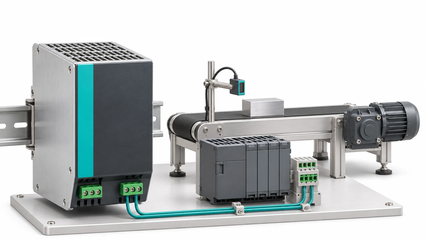
Choosing the right DC supply for a control cabinet
Siemens SITOP is a family of regulated industrial DC power supplies, DC UPS solutions and complementary modules. With the appropriate model, SITOP power supplies can supply a PLC, operator panel, sensors and control circuits. 24 V DC control power is a common application, although other output voltages are also available.
Editor’s note: SITOP is a product family, not a single model. Units can differ in input voltage, output current, overload behavior and communications. Use the complete order number when checking replacements or equivalents. The name “Modular” does not mean that every unit can gain additional current capacity by attaching a module.
What do the different families offer?
SITOP Compact covers compact solutions for space-constrained, lower-power applications. SITOP Smart is a standard range for general industrial supplies. SITOP Modular / PSU8200 addresses more demanding load behavior and power-reserve requirements. These names alone do not establish a particular current rating, input range or communication interface.
The current portfolio includes SITOP PSU4200 for basic cabinet supplies and PSU6200 for standard industrial applications. PSU6200 diagnostics and power-reserve features depend on the model. PSU8400 provides parameterization and diagnostics through IO-Link.
SITOP PSU8600 supports system-level supply management through monitored, adjustable outputs, compatible expansion components and PROFINET / OPC UA communication. These capabilities do not apply to every SITOP product. Complete the selection by checking the technical data for the actual model.
How the supply works and which input it requires
AC-input SITOP supplies use switched-mode power conversion and feedback to produce a regulated DC output. A switched-mode power supply differs from a conventional transformer-based adapter. DIN rail mounting is common in control cabinets, and the specified ventilation clearances must be maintained.
A single-phase 24 V DC supply and a three-phase power supply require different mains connections. Check the input range, phase requirements and permitted connection arrangement on the nameplate and in the manual. Matching output-current ratings alone do not make two units interchangeable.
UPS, buffering, redundancy and selectivity serve different purposes
A DC UPS is an uninterruptible power solution that uses an energy-storage component to support DC loads during an outage. Solutions such as SITOP UPS1600 require a compatible battery module and the appropriate interface variant. Depending on the application, the aim is continued operation or time for a controlled shutdown. Runtime depends on load, storage capacity, temperature and aging.
A buffer module uses energy stored in capacitors to bridge brief supply interruptions. Select it against the required duration and load current; buffering time is not a fixed value. These SITOP complementary modules serve a different duty from a battery-backed UPS sized for a longer outage.
A redundancy module decouples two supply outputs to help prevent a faulty source from affecting the healthy one. For 1+1 redundancy, either supply must be able to carry the entire load under the required operating conditions. Two 10 A supplies powering an 18 A load do not provide 1+1 redundancy. If both lose their common mains source, redundancy without energy storage cannot maintain the load.
A selectivity module distributes DC power across individual load circuits and aims to disconnect a branch experiencing overload or a short circuit. For example, a faulty valve circuit should be isolated before it collapses the PLC supply. Performance depends on the supply’s current characteristic, protection module, settings and wiring. A supply with short-circuit protection does not automatically provide selective protection for every branch.
How much output current is required?
Add the maximum DC currents of loads that operate simultaneously. For a basic watts-to-amperes calculation, use P = V × I. For example, a PLC drawing 0.6 A, an HMI drawing 0.8 A, sensors drawing 0.4 A and a relay-and-valve group drawing 1.6 A total 3.4 A, or approximately 81.6 W at 24 V.
An illustrative 25% operating allowance gives 4.25 A, making a 5 A supply an initial candidate. Startup current, simultaneous coil energization, capacitive loads, future expansion and temperature derating still require separate checks. Power Boost or Extra Power is not a substitute for continuous output-current capacity.
Installation and fault-finding checks
A 24 V reading at the supply is insufficient on its own: also measure voltage at the load terminals while the equipment operates. Long or undersized cables and loose connections can cause voltage drop. When investigating PLC resets or unstable sensors, correlate voltage fluctuations with the moment each load switches on.
Where available, connect the DC OK contact or diagnostic interface to the control system so supply problems can be detected. Follow the manual for mounting orientation, ventilation, protective earthing, input protection and terminal torque. Efficiency also affects cabinet heat losses. Check applicable power-supply standards and approvals against the selected order number rather than assuming they cover the whole family.
Related pages
SITOP power supplies / DIN rail power supplies / Uninterruptible power supplies / Power supply overview