
Simatic S5 Cables/Connectors
Siemens SIMATIC S5 Cables, Front Connectors and Connection Accessories
Siemens SIMATIC S5 cables and connectors cover field wiring for I/O modules, connections between central and expansion racks, PG programming links and legacy communication networks. This section includes 490 and 497 front connectors, 705–736 connecting cables and SINEC L2-DP accessories.
Compare the complete models at both ends, port names, electrical interfaces, pin assignments and cable length. Identical D-sub housings can carry different TTY, RS-232 or RS-485 signals. The “S5 90/110” category path does not establish compatibility of every listed part with those systems.
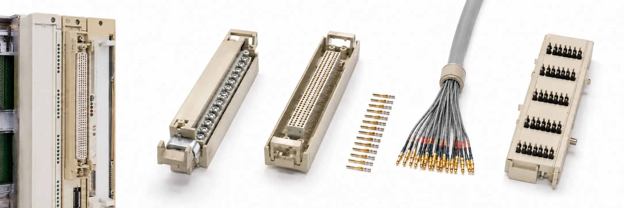
490-7 front connectors and input simulators
6ES5 490-7LA11 is supplied with 50 crimp contacts; 6ES5 490-7LA21 is the version without contacts. For screw connections, 6ES5 490-7LB11 is the 24-pole option and 6ES5 490-7LB21 the 46-pole option. Compare the contact arrangement and terminal numbering with the module wiring diagram.
6ES5 490-7SA11 is a 32-switch/button input simulator; 6ES5 490-7SA21 is a 16-switch/button simulator. They provide test inputs for compatible input modules. Confirm the simulator voltage and module pairing before connecting it.
490-8 connections: crimp, screw and special versions
6ES5 490-8MA03, 6ES5 490-8MA11, 6ES5 490-8MA12 and 6ES5 490-8MA13 are separate versions in the 490-8MA crimp front connector group. 6ES5 490-8MB11 is a 40-pin screw connector and 6ES5 490-8MB21 a 20-pin screw connector. Confirm included crimp contacts, missing terminal parts and the actual hardware version for each item.
6ES5 490-8FB11 belongs to the S5-95F front connection accessory group; compare the 490-8MD terminal block 6ES5 490-8MD11 separately. A matching pin count alone does not establish interchangeability with a standard 490-8MA or 8MB connector.
497 front connector widths and terminals
6ES5 497-4UA12 is a 42-way crimp connector for a 20 mm mounting width. 6ES5 497-4UB12 is the 42-way screw version for 40 mm, while 6ES5 497-4UB31 is the 42-way screw version for 20 mm. Check conductor sizes, jumpers and the module ventilation arrangement as well.
6ES5 497-4UB11, 6ES5 497-4UB22 and 6ES5 497-4UB42 are other 497-4UB connector variants. Verify their contact counts and dimensions individually rather than applying the 4UB12 or 4UB31 specifications. Compare the original nameplate and the relevant module socket.
Centralized and short-distance rack connections
6ES5 705-0AF00, 6ES5 705-0BB20, 6ES5 705-0BB50 and 6ES5 705-0BC50 belong to the 705-0 centralized expansion cable group. Select the cable with the applicable IM modules and rack layout. 6ES5 711-0AD20 and 6ES5 713-0AD20 are separate 711/713 rack connecting cables; similar lengths do not establish equivalent connections.
6ES5 716-0AK00 and 6ES5 716-0BB50 belong to the 716 group; 6ES5 717-0BJ00 to 717 and 6ES5 718-0AF00 to 718. For these older controller connections, establish the CC/EU arrangement, opposite module, connector orientation and actual cable length.
6ES5 712-8AF00 and 6ES5 712-8BC50 are the 0.5 m and 2.5 m cables for IM 316 tier expansion. 6ES5 308-3UA12 is an IM 308 interface module, rather than a passive cable. Its line and opposite interface must be selected separately.
721 distributed expansion cables
6ES5 721-0BB00, 6ES5 721-0BB60, 6ES5 721-0BC00, 6ES5 721-0BC50, 6ES5 721-0BD20, 6ES5 721-0BF00 and 6ES5 721-0CB60 are different length codes in the 721-0 distributed rack cable family. Permissible distance depends on the IM modules and complete installation. A documented 600 m system limit does not mean each cable is 600 m long or that every IM pairing supports that distance.
CP connections, SINEC H1 and peripheral equipment
6ES5 725-0AK00 and 6ES5 725-1AK00 belong to the 725 group; 6ES5 725-7CC50 to 725-7. 6ES5 726-1BF00, 6ES5 726-1CB00 and 6ES5 726-8BC00 are in the 726 CP connection group. Match the CP model, TTY/RS-232/RS-422 interface and opposite device port using the complete order number.
6ES5 727-1BD20, 6ES5 727-1CB00 and 6ES5 727-1CD20 are SINEC H1 727-1 cables with respective lengths of 3.2 m, 10 m and 32 m. Legacy H1 transceiver connections must be distinguished from modern RJ45 connections. 6ES5 727-2CB00 and 6ES5 727-3CE00 are separate 727-2/727-3 special connection variants requiring their own equipment pairing.
6ES5 730-1BF00 belongs to the 730 programmer/peripheral connection group. 6ES5 735-1BD20, 6ES5 735-1BF00 and 6ES5 735-2BD20 are 735 printer cables; 6ES5 736-2CB00 and 6ES5 736-2CC00 are 736 display/operator equipment cables. Confirm electrical interfaces and pin assignments even when a printer or monitor has a physically similar socket.
PG programming cables: 731, 733 and 734
6ES5 731-0BD20 and 6ES5 731-0BF00 belong to the 731-0 group; 6ES5 731-1BD20, 6ES5 731-1BF00 and 6ES5 731-1CB00 to 731-1 PG–AS 511 connections. 6ES5 731-7AG00 is a 731-7 interface adapter; 6ES5 733-2BD20 and 6ES5 733-2CB00 are 733-2 programmer cables. Check the 15/25-pin programmer connection and any required adapter.
6ES5 734-0BD20 is a 734-0 legacy PG connection. 6ES5 734-2BD20 and 6ES5 734-2BF00 are 3.2 m and 5 m 734-2 cables. 734-2BD20 connects a TTY-equipped PG/HMI to the S5 TTY programming port. A PC with only an RS-232 port requires the appropriate electrical conversion.
The CL/clone listings 6ES5 734-1BD20-CL and 6ES5 734-2BF00-CL require their own identification. Siemens’ original 734-1BD20 designation identifies a connection with RS-232/TTY conversion. The manufacturer, circuitry, isolation and actual length of a CL-suffixed product cannot be inferred from that name. State the actual item label and verified connection test scope in the quotation.
Encoder cable and mounting accessories
6ES5 703-4CB01 belongs to the 703-4 encoder cable group. Compare encoder supply, signal levels and the IP module connections. 6ES5 710-8MA31 is a 710 mounting rail. 6ES5 728-8MA11 is a ground terminal for connecting a cable shield to the grounded rail, rather than a programming terminal.
SINEC L2-DP bus connectors and ET 200C connections
6ES5 762-1AA12 and 6ES5 762-2AA12 are SINEC L2 bus connectors without a PG socket; 6ES5 762-1AA21 and 6ES5 762-2AA21 include a PG socket. Check bus speed, termination switching, cable entry and mechanical clearance. Do not assign the same maximum transmission rate to every legacy L2 connector.
6ES5 760-2CB11 is a 12-pin circular bus/power connector with a pin insert. 6ES5 762-2CT11 is the SINEC L2-DP T connector for ET 200C, with two 12-pin sockets and one 12-pin male connection. These components must not be selected as protocol converters or generic IM rack terminators.
Inspecting used cables and connectors
Provide the complete model, quantity, working/faulty condition, nameplate and both-end photographs, actual length and price. Inspect broken latches, missing pins, later splices, hardened insulation, damaged shield connections and missing crimp contacts before delivery.
Editor’s note
Start by identifying exactly what connects to each end. “S5 cable” alone is insufficient. Record the CPU/CP model and port name; photographs of both connectors and the nameplate make selection much easier.
Distinguish TTY from RS-232 by the electrical interface. Check where any required conversion takes place before using a 734-2 connection. For a clone cable, establish its actual circuitry and ask which connection has been tested.
Inspect contact retention, screws, latches and terminal numbering, as well as the front connector housing. A missing crimp contact or damaged terminal can make a working module appear faulty. Isolate power before working on module and field connections.
Consider the IM pairing, total line length and termination together. Avoid undocumented extensions. Record shield connections and which bus connectors have termination enabled before disturbing an existing installation.
An end-to-end continuity check is useful, but does not establish reliable communication under operating conditions. Test with the relevant PG/CPU or suitable test equipment where possible. Adapt the test method to any electronics inside an active converter cable.
Agree the included parts and test scope before buying used equipment. Workshop testing is possible, with the method determined by the available hardware. All sales require an invoice; returns are not accepted. To offer S5 cables and connectors for sale, send the model, quantity, condition, photographs and asking price to otomasyonavm@gmail.com.
OtomasyonAVM resources and PDFs
Identify the host system through About Siemens S5 PLCs, the SIMATIC S5 main page and S5 CPU models. Use the S5 system manuals and PDF files archive to find a wiring diagram matching the complete module code and document edition.
Related topics
Review S5 interface modules, S5 racks and mounting frames, S5 central and expansion units, S5 positioning modules, S5 special modules and S5 power supplies when selecting connecting equipment.
Browse SIMATIC S5
+ SIMATIC S5 | Siemens S5 PLCs | S5 module groups | Used Siemens equipment | All used equipment
Siemens and external references
+ S5-115U Programmable Controller Manual — EWA 4NEB 811 6130-02b, Edition 04; English.
+ S5-100U Programmable Controller System Manual — EWA 4NEB 812 6120-02b, Edition 04; English.
+ S5-135U/155U System Manual — C79000-G8576-C199-07; English.
+ SIMATIC S5 U Periphery Manual and Supplement — 6ES5 998-0PC22; C79000-Q8576-C017-03; English.
+ WinCC flexible 2008 Communication Part 1 — A5E01056780-02; sections 7.5.2–7.5.3; English.
+ SINEC L2-DP Interface on the S5-95U — EWA 4NEB 813 6013-02a; Appendix C; English.
+ SINEC L2-DP with IM 328-N Module — 6ZB5 430-0BH02-1AA0; 07.96, section 2.1.2; English.
+ ET 200C Distributed I/O Station Manual — EWA 4NEB 812 6119-02b; section 3.8; English.
+ DP/AS-i Link Distributed I/O System Manual — EWA 4NEB 710 6055-02b; section 4.4.7; English.
+ SIMADYN D Hardware — SINEC H1 CSH11 — Section 6.2; printed 6-9; German.
+ SIMATIC S5-95F Product Family — Accessories — Siemens product-family certificate; page 4; English.
+ Siemens WT10 — SIWAREX WP251 Accessories — WT10, 2020; printed 2/35; English.