
What is phase Protection Relay?
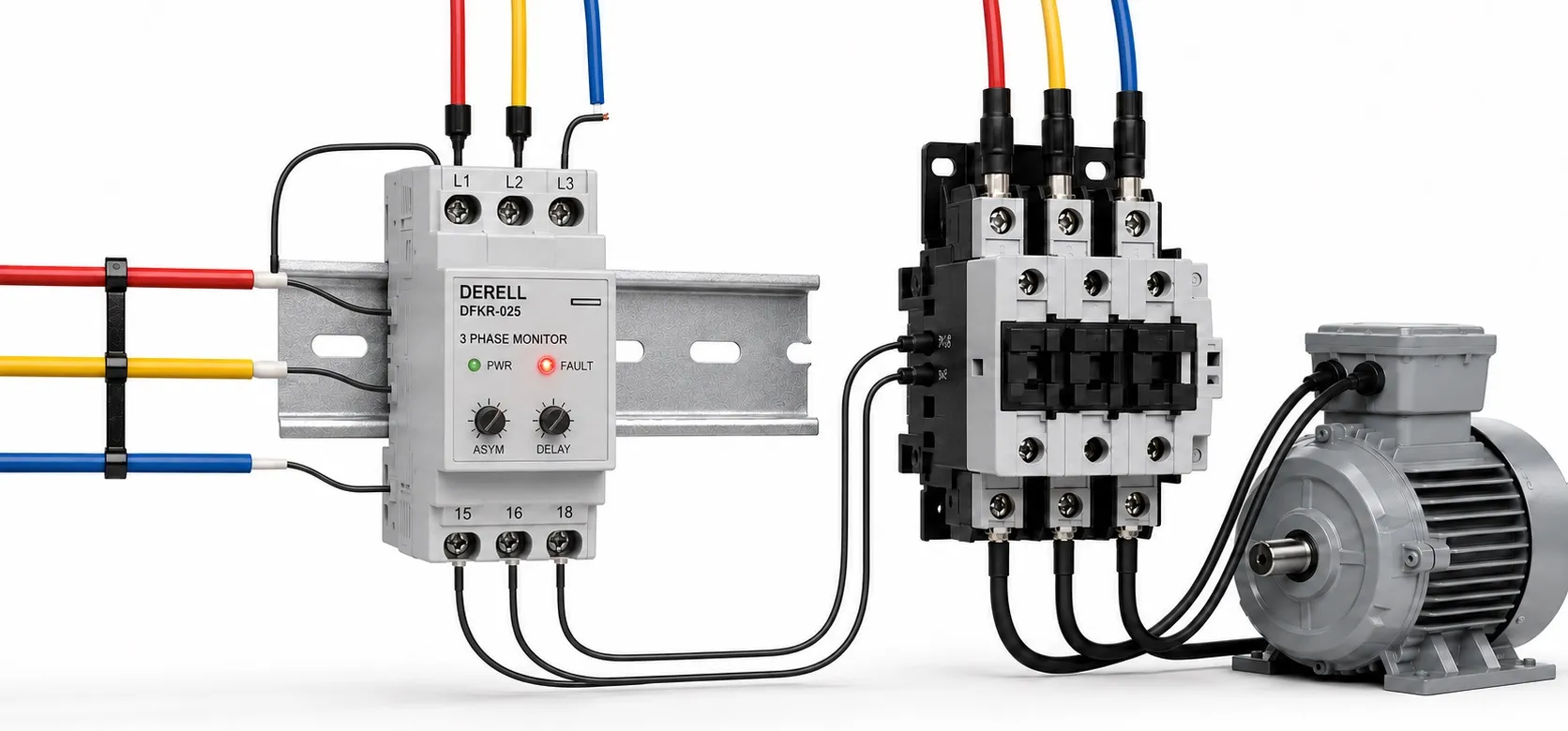
What is a phase protection relay?
A phase protection relay, also called a phase monitoring relay, monitors a three-phase supply and changes its output contact when it detects an unacceptable condition. It provides a monitoring and protection function. Common voltage-monitoring models check L1, L2 and L3. Phase protection relays are used in panels for pumps, compressors, fans and production machinery with three-phase motors.
Which faults can it detect?
Phase loss: This can result from an interrupted phase, an open fuse or a connection fault. Following phase loss, a motor may fail to start or continue rotating while overheating. A motor that is still turning is not necessarily receiving a healthy supply.
Incorrect phase sequence: A change in supply phase sequence can reverse a motor connected directly to the mains. A relay with sequence monitoring prevents operation with the wrong sequence. A phase sequence tester is a separate measuring instrument used during inspection and commissioning.
Voltage imbalance: Unequal phase voltages can increase motor current imbalance and heating. Undervoltage or overvoltage: Models offering these functions detect a supply outside the selected limits. Assess voltage protection thresholds and the imbalance calculation method using the manufacturer's documentation.
Neutral loss: Monitoring requires a suitable measurement arrangement and an explicit neutral-loss function. Phases, neutral and protective earth have different roles. A three-wire relay without a neutral connection should not be assumed to detect a broken neutral.
How does it work with a contactor?
In a typical motor control circuit, the output contact of the relay provides a run permissive to the contactor coil circuit. With a healthy supply, operation is permitted. A monitored fault removes that permission, de-energising the coil and opening the contactor's main power contacts. The contactor carries the motor current. This explains the difference between a relay and a contactor.
The diagram illustrates the operating relationship, not installation wiring. Fuses, overload protection and other control devices have been omitted for clarity. Actual wiring must follow terminal markings, coil voltage and the manufacturer's diagram. NO and NC describe the relay contacts in their de-energised state.
Does it replace an overload relay or fuse?
No. An overload relay protects against overheating caused by overload; some motor protection devices also detect phase loss from current measurements. A fuse or suitable circuit breaker provides short-circuit protection. Phase monitoring can work alongside these devices. Monitoring motor temperature with a PTC sensor is another distinct protection approach.
A phase monitoring relay is neither residual-current protection nor a surge protective device. Voltage monitoring and surge protection address different problems. An ordinary phase monitoring relay should not be treated as a machine safety relay on its own. Assess the machine's electrical equipment when designing control and restart behaviour.
Does a healthy supply guarantee a healthy motor circuit?
Not always. A relay measuring voltage upstream of the contactor may not detect a failed main contact or broken motor cable downstream. A rotating motor can also induce voltage at a missing-phase terminal, limiting phase-loss detection in some voltage-only models. Appropriate motor protection and motor-side current monitoring therefore remain important.
What changes when the motor uses a drive?
In a panel with a variable frequency drive, a mains input fault differs from a fault at the inverter's motor output. Supply phase sequence does not directly determine motor direction as it does for a directly connected motor. Do not connect a mains monitoring relay to a drive's PWM output unless the manufacturer explicitly approves that use. Design stop commands and contactor operation according to the drive's installation instructions.
What matters when selecting and setting the relay?
Select measurement voltage, supply frequency, three-wire or neutral-connected arrangement, required functions and output contact rating together. The relay's measurement range is distinct from the contactor coil voltage. A contact's ampere rating does not mean a motor can be connected directly; use the specified switching capacity for the inductive coil load.
Trip delay can reduce nuisance trips from brief voltage disturbances, but excessive delay can weaken protection. Recovery delay and hysteresis help prevent repeated switching. Phase-loss and voltage-fault response times may differ. There is no single threshold or delay suitable for every installation.
What should be checked when a fault is indicated?
Read the fault indication and settings first. A qualified person checks voltage and phase sequence at the relay's measurement point with a suitable measuring instrument, then assesses fuses, connections and the contactor. Wire colour alone does not prove correct phase identification. Isolate the circuit and verify absence of voltage before installation or wiring work.
A relay returning to its healthy state should not, by itself, cause an unsafe automatic machine restart. Restart must depend on the application's safe control conditions. Correct the fault rather than bypassing the relay. A smart relay or SCADA can record faults, but logging and alarms do not replace the required physical protection.
Technical references: ABB: Three-phase monitoring · ABB: CM-PFS · Schneider Electric: Harmony · OMRON: K8DS-PM · OMRON: K8DS-PH