
Omron E7 Fault index
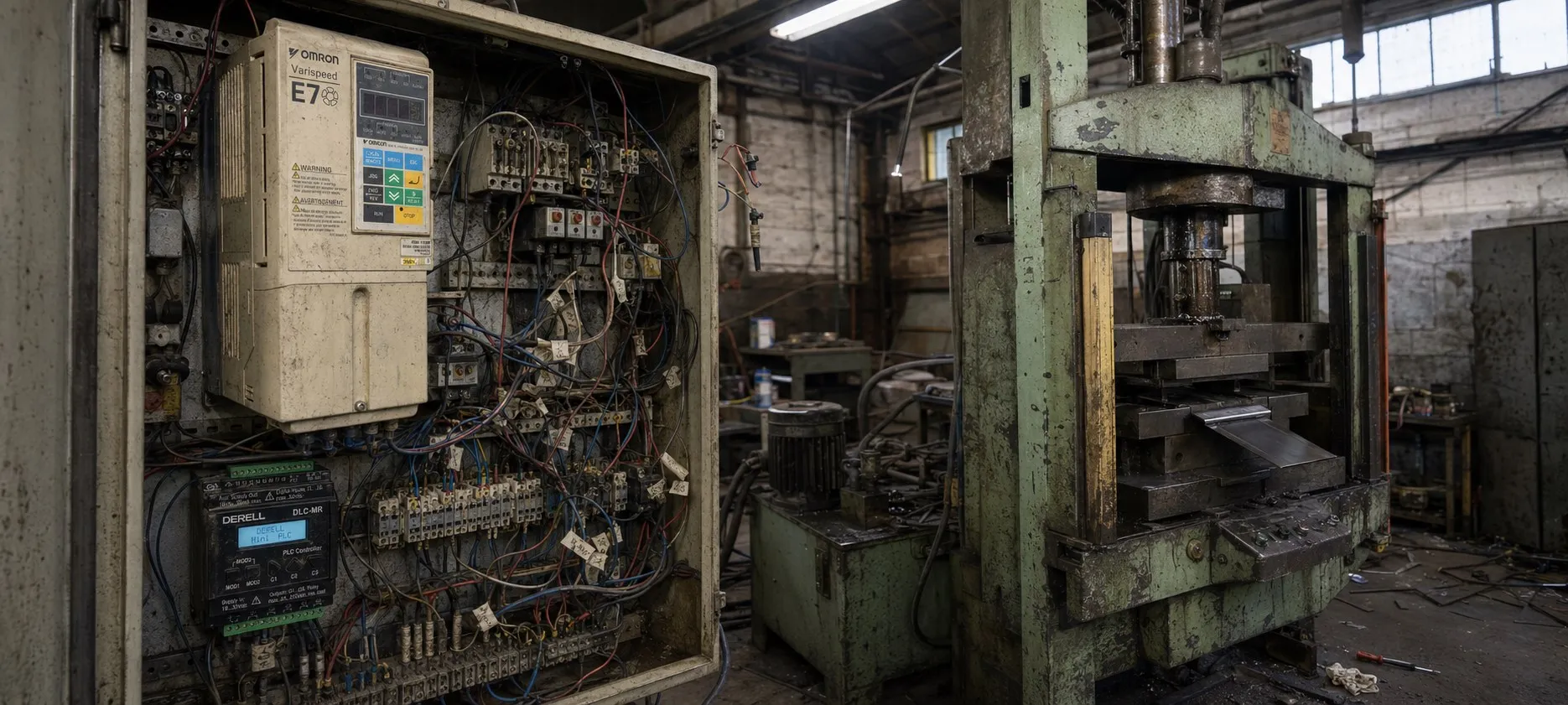
If Parameters Cannot Be Adjusted
The Display Doesn’t Change (Nothing Happens When Pressing Increase or Decrease Buttons):
+ Possible Causes:
The inverter may be running. Some parameters cannot be adjusted while the device is operating. Turn off the RUN command, then make the adjustments.
Parameter write permission might not have been enabled. If "parameter write permission" is set for one of the multifunction input terminals (H1-01 to H1-05), parameters cannot be changed when this permission is disabled. Enable write permission and try adjusting the parameters again.
Passwords may not match. If a password is set and the numbers in A1-04 (Password) and A1-05 (Password Setting) are not the same, parameters cannot be adjusted. Reset the password.
If you don’t remember your password: While on the A1-04 screen, press the RESET and MENU buttons simultaneously. The A1-05 screen will appear, where you can reset the password.
If an Error Between OPE01 and OPE11 is Displayed:
+ There is an error in the parameter settings. Correct the settings according to the error codes.
If CPF00 or CPF01 Error is Displayed:
+ This is a communication error between the Digital Operator and the Inverter. Disconnect and reconnect the Digital Operator.
Protection and Diagnosis Functions
This section explains the alarm functions of the inverter. The alarm functions include fault detection, alarm detection, operational error detection, and autotuning error detection.
Fault Detection
When the inverter detects a fault, the fault output activates, and the inverter output shuts off, causing the motor to stop freely. (For some faults, the stop method can be selected.)
A fault code is displayed on the Digital Operator screen.
When a fault occurs, refer to the table to correct the error and its cause.
Before restarting the inverter, you can reset the fault using one of the following methods:
+ Set one of the multifunction input contacts (H1-01 to H1-05) to 14 (Fault Reset) and activate the fault reset signal.
+ Press the RESET button on the Digital Operator.
+ Turn the main circuit power supply off and on again.
oC (Overcurrent): The inverter's output current exceeded the detected overcurrent level. (Details >>)
GF (Ground Fault): A ground fault occurred in the inverter output. (Details >>)
P_uF (Fuse Blown): The main circuit fuse has blown. (Details >>)
oU (Main Circuit Overvoltage): The main circuit DC voltage exceeded the overvoltage detection level. (Details >>)
u_u1 (Main Circuit Undervoltage): The main circuit DC voltage dropped below the undervoltage detection level. (Details >>)
u_u2 (Control Power Fault): A voltage drop occurred in the control power supply. (Details >>)
u_u3 (Inrush Current Prevention Circuit Fault): The inrush current prevention circuit overheated. (Details >>)
PF (Main Circuit Voltage Fault): The DC voltage in the main circuit is fluctuating abnormally. (Details >>)
oH (Cooling Fin Overheating): The inverter’s cooling fin temperature exceeded the set limit. (Details >>)
oH1 (Inverter Cooling Fan Stopped): The internal cooling fan of the inverter stopped. (Details >>)
oH3 (Motor Overheating Alarm): The inverter will stop or continue operating when the motor overheats. (Details >>)
oH4 (Motor Overheating Fault): The inverter will stop when the motor overheats. (Details >>)
oL1 (Motor Overload): The motor overload protection function was activated based on internal motor temperature. (Details >>)
oL2 (Inverter Overload): The inverter overload protection function was activated based on internal inverter temperature. (Details >>)
oL3 (Overtorque Detected 1): Torque exceeding the limit was applied for longer than the set time. (Details >>)
oL7 (High-slip Braking OL): The output frequency did not change within the set time. (Details >>)
UL3 (Undertorque Detected 1): Torque below the set level was applied for longer than the set time. (Details >>)
FbL (PI Feedback Lost): PI feedback loss was detected. (Details >>)
EF0 (External Fault Input from Communications Option Card): External fault input detected. (Details >>)
EF3 - EF7 (External Fault): External fault input detected from multifunction input terminals. (Details >>)
oPr (Digital Operator Connection Fault): The connection to the digital operator was lost during operation. (Details >>)
CE (MEMOBUS Communications Error): No valid data received for over 2 seconds after control data was received. (Details >>)
bUS (Option Communications Error): Communication error detected with the Option Card during a RUN command. (Details >>)
CPF00 (Digital Operator Communications Error 1): Unable to communicate with the Digital Operator within 5 seconds of power-up. (Details >>)
CPF01 (Digital Operator Communications Error 2): Communication with the Digital Operator was lost for over 2 seconds. (Details >>)
CPF02 (Baseblock Circuit Error): An error occurred in the baseblock circuit. (Details >>)
CPF03 (EEPROM Error): An error occurred in the EEPROM. (Details >>)
CPF04 (CPU Internal A/D Converter Error): An error occurred in the CPU’s internal A/D converter. (Details >>)
CPF05 (CPU External A/D Converter Error): An error occurred in the CPU’s external A/D converter. (Details >>)
CPF06 (Option Card Connection Error): The option card is not properly inserted. (Details >>)
CPF07 (ASIC Internal RAM Fault): An error occurred in the internal RAM of the ASIC. (Details >>)
CPF08 (Watchdog Timer Fault): An error occurred in the watchdog timer. (Details >>)
CPF09 (CPU-ASIC Mutual Diagnosis Fault): An error occurred during mutual diagnosis between the CPU and ASIC. (Details >>)
CPF10 (ASIC Version Fault): There is an error in the version of the ASIC. (Details >>)
CPF20 (Communications Option Card A/D Converter Error): An error occurred in the A/D converter of the Communications Option Card. (Details >>)
CPF21 (Communications Option Card Self Diagnostic Error): An error occurred during the self-diagnosis of the Communications Option Card. (Details >>)
CPF22 (Communications Option Card Model Code Error): There is an error with the model code of the Communications Option Card. (Details >>)
CPF23 (Communications Option Card DPRAM Error): An error occurred in the DPRAM of the Communications Option Card. (Details >>)
Er-01 (Motor Data Error): There is an error in the data entered for autotuning. (Details >>)
Er-02 (Alarm): A minor error occurred during autotuning. (Details >>)
Er-03 (STOP Key Input): The STOP key was pressed to cancel autotuning. (Details >>)
Er-04 (Line-to-line Resistance Error): Autotuning was not completed within the set time. (Details >>)
End3 (Rated Current Setting Alarm): The rated current setting is too high. (Details >>)
oPE09 (PI Control Selection Error): Several conflicting settings have been made simultaneously. (Details >>)
oPE10 (V/f Data Setting Error): Parameters do not meet the required conditions. (Details >>)
oPE11 (Parameter Setting Error): A parameter setting error is present. (Details >>)
Err (EEPROM Write Error): A verification error occurred while writing to the EEPROM. (Details >>)
oPE01 (Incorrect Inverter Capacity Setting): The inverter capacity setting does not match the device. (Details >>)
oPE02 (Parameter Setting Range Error): The parameter setting is outside the valid range. (Details >>)
oPE03 (Multi-function Input Selection Error): An error was made in the multi-function input settings. (Details >>)
oPE05 (Option Card Selection Error): An option card was selected as the frequency reference source, but the card is not connected. (Details >>)