
Omron 3G3rV fault codes
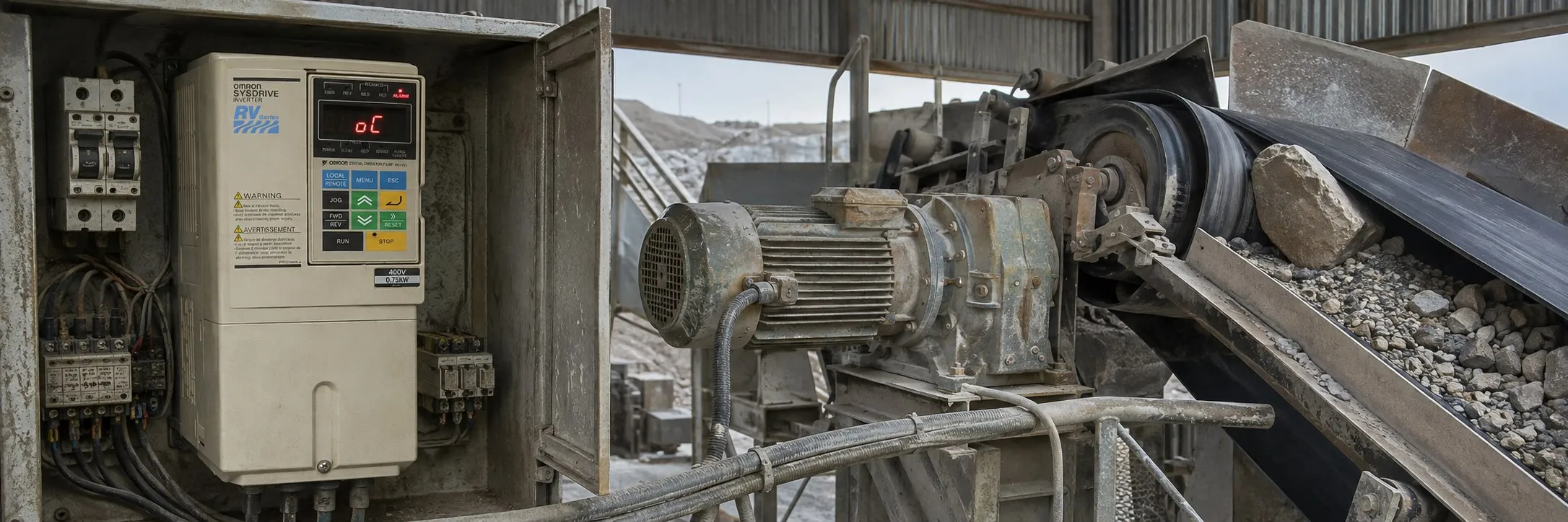
When starting up the system, incorrect parameter settings or faulty wiring may cause the inverter and motor to not operate as expected. Refer to this section for appropriate measures if this occurs. For fault details, see Protective and Diagnostic Functions.
If Parameters Cannot Be Set:
- If the display doesn't change when pressing the keys, check if the inverter is operating, if parameter write enable is off, or if passwords don't match.
- For display errors OPE01 to OPE11, correct the parameter settings.
- For CPF00 or CPF01 errors or a blank Digital Operator display, check the communication connection.
If the Motor Does Not Operate:
- Check the operation method setting, frequency reference, multi-function analog input settings, and control circuit terminal wiring.
- For external operation signal issues, ensure the inverter is in drive mode, check operation method selection, and verify input terminal status.
If Motor Rotation Direction is Reversed:
- Check motor output wiring and consider switching two wires among U, V, and W.
If Motor Lacks Torque or Acceleration is Slow:
- Check torque limit settings, stall prevention levels, and consider autotuning for vector control.
If Motor Operates Higher Than Reference:
- Check analog frequency reference bias and signal input to the frequency reference terminal.
If Slip Compensation Function Has Low Speed Precision:
- Check the slip compensation limit setting.
If Low Speed Control Accuracy at High-Speed Rotation in Open-loop Vector Control Mode:
- Consider using a motor with a lower rated voltage or switch to flux vector control.
If Motor Deceleration is Slow:
- Check deceleration time settings, torque limits, and ensure proper brake sequence and DC braking settings.
If Motor Overheats:
- Check the load size, ambient temperature, and motor's withstand voltage. Consider autotuning for vector control.
If There is Noise When Inverter Starts or From an AM Radio:
- Lower the carrier frequency, install input and output noise filters, use metal tubing for shielding, and ensure proper grounding.
Protective and Diagnostic Functions
This section covers the alarm functions of the inverter, including fault detection, alarm detection, operation error detection, and autotuning error detection.
Fault Detection
When a fault is detected, the inverter's fault contact output activates, shutting off the output and causing the motor to coast to a stop. (For some faults, a specific stopping method can be selected and will be used.) A fault code is displayed on the Digital Operator.
To identify and correct the cause of a fault, refer to the fault table. After addressing the issue and restarting the inverter, reset the fault using one of the following methods:
- Set a multi-function contact input (H1-01 to H1-05) to 14 (Fault Reset) and activate the error reset signal.
- Press the RESET Key on the Digital Operator.
- Turn the main circuit power supply OFF and then ON again.
Fault Displays and Processing
oC - Overcurrent: This error indicates that the output current of the inverter has exceeded 200% of the rated current.
This can happen due to a short-circuit or ground fault at the inverter output, possibly caused by motor burn damage, worn insulation, or a damaged cable. It could also occur if the load is too large or if the acceleration/deceleration time is too short. To fix this, check for any short circuits or ground faults, adjust the load or timing settings, and reset the fault.
GF - Ground Fault: This error occurs when the ground fault current at the inverter output exceeds approximately 50% of the rated output current.
Similar to the overcurrent fault, this can be caused by motor burn damage, worn insulation, or a damaged cable. To resolve this issue, identify and correct the ground fault, then reset the fault.
PUF - DC BUS Fuse Open: This error indicates that the fuse in the main circuit has blown, likely due to a short-circuit or ground fault at the inverter output.
Check for any short circuits between the terminals (B1, U, V, W) and replace the inverter after correcting the cause.
ou - DC Bus Overvolt: This error occurs when the main circuit DC voltage exceeds the overvoltage detection level (approximately 410V for 200V class and 820V for 400V class).
This can happen if the deceleration time is too short and the regenerative energy from the motor is too large, or if the power supply voltage is too high. To fix this, increase the deceleration time, connect a braking resistor, or decrease the power supply voltage to within specifications.
Uu1 - DC Bus Undervolt: This error indicates that the main circuit DC voltage is below the undervoltage detection level.
It can occur due to an open-phase in the input power supply, a momentary power loss, loose wiring terminals, large voltage fluctuations in the input power supply, or a fault in the surge prevention circuit. To resolve this, check the input power supply, wiring terminals, and surge prevention circuit, then reset the fault after correcting the cause.
Uu2 - Control Power Fault: This error occurs when the control power supply voltage drops.
To fix this, try turning the power supply off and on. If the fault continues to occur, replace the inverter.
Uu3 - Inrush Prevention Circuit Fault: This error indicates overheating in the inrush resistor and that the MC (Main Circuit) did not respond for 10 seconds even though the MC ON signal has been output.
This can happen if the MC in the main circuit failed or the MC excitation coil is burned out. Try turning the power supply off and on, and if the fault persists, replace the inverter.
PF - Main Circuit Voltage Fault: This error occurs when the main circuit DC voltage oscillates unusually (not during regeneration).
It can be caused by an open-phase in the input power supply, a momentary power loss, loose wiring terminals, large voltage fluctuations in the input power supply, or poor voltage balance between phases. Reset the fault after correcting the cause.
LF - Output Open-phase: This error indicates an open-phase at the inverter output.
This can be caused by a broken wire in the output cable or motor winding, or loose output terminals. Reset the fault after correcting the cause. Also, ensure that the motor being used has a capacity of at least 5% of the inverter's maximum motor capacity.
oH and oH1 - Heatsink Overtemp: These errors occur when the temperature of the inverter's cooling fins exceeds the setting in L8-02 or 105°C.
"oH" indicates the temperature exceeded the setting in L8-02, and "oH1" indicates the temperature exceeded 100°C. This can happen if the ambient temperature is too high, there is a heat source nearby, or the inverter's cooling fan has stopped. To fix this, install a cooling unit, remove the heat source, or replace the cooling fan.
oH3 - Motor Overheat 1: This error indicates that the motor has overheated, which can trigger a stop or continue operation based on the setting of L1-03.
To resolve this, check the size of the load and the length of the acceleration, deceleration, and cycle times. Also, verify the V/f characteristics and the motor temperature input on terminals A1 and A2.
oH4 - Motor Overheat 2: Similar to oH3, this error indicates motor overheating, but the inverter will stop according to the setting of L1-04.
The same checks as for oH3 should be performed to correct the issue.
rH - Installed Braking Resistor Overheating: This error occurs when the braking resistor is overheated, and the protection function has operated if enabled in L8-01.
To fix this, reduce the load, increase the deceleration time, reduce the motor speed, or switch to a Braking Resistor Unit.
rr - Internal Braking Transistor Fault: This error indicates a malfunction in the braking transistor.
Try turning the power supply off and on, and if the fault persists, replace the inverter.
oL1 - Motor Overloaded: This error occurs when the motor overload protection function has operated based on the internal electronic thermal value.
To resolve this, check the size of the load, the length of the acceleration, deceleration, and cycle times, and the V/f characteristics. Also, ensure that the Motor Rated Current (E2-01) is set correctly.
oL2 - Inverter Overloaded: This error indicates that the inverter overload protection function has operated based on the internal electronic thermal value.
To fix this, check the size of the load, the length of the acceleration, deceleration, and cycle times, and the V/f characteristics. If necessary, replace the inverter with one that has a larger capacity.
oL3 - Overtorque Detected 1: This error occurs when there has been a current greater than the setting in L6-02 for longer than the setting in L6-03.
To resolve this, ensure that the settings in L6-02 and L6-03 are appropriate and check the mechanical system to correct the cause of the overtorque.
oL4 - Overtorque Detected 2: Similar to oL3, this error occurs when there has been a current greater than the setting in L6-05 for longer than the setting in L6-06.
Ensure that the current setting in L6-05 and time setting in L6-06 are appropriate, and check the mechanical system to correct the cause of the overtorque.
oL7 - High-slip Braking Overload: This error occurs when the output frequency does not change for longer than the time set in N3-04.
This can happen if the inertia returned to the load is too large. Ensure that the load is an inertial load and set the system so that the deceleration time that does not produce 0V is 120 seconds or less.
UL3 - Undertorque Detected 1: This error occurs when there has been a current less than the setting in L6-02 for longer than the setting in L6-03.
Ensure that the settings in L6-02 and L6-03 are appropriate and check the mechanical system to correct the cause of the undertorque.
UL4 - Undertorque Detected 2: Similar to UL3, this error occurs when there has been a current less than the setting in L6-05 for longer than the setting in L6-06.
Ensure that the current setting in L6-05 and time setting in L6-06 are appropriate and check the mechanical system to correct the cause of the undertorque.
oS - Overspeed Detected: This error occurs when the speed has been greater than the setting in F1-08 for longer than the setting in F1-09.
To resolve this, adjust the gain again if overshooting/undershooting is occurring, check the reference circuit and reference gain if the reference speed is too high, and ensure that the settings in F1-08 and F1-09 are appropriate.
PGO - PG Open: This error indicates a PG disconnection detected, which occurs when PG pulses were input when the inverter was outputting a frequency (soft start output ≥ E1-09).
To fix this, check for a break in the PG wiring, ensure proper wiring of the PG, supply power to the PG properly, and check for an open circuit when using a brake (motor).
dEu - Excessive Speed Deviation: This error occurs when the speed deviation has been greater than the setting in F1-10 for longer than the setting in F1-11.
To resolve this, reduce the load if it's too heavy, lengthen the acceleration and deceleration times if they are too short, check the mechanical system if the load is locked, and ensure that the settings in F1-10 and F1-11 are appropriate.
CF - Control Fault: This error indicates that the torque limit was reached continuously for 3 seconds or longer during a deceleration stop during open-loop vector control.
Check the motor constants to resolve this issue.
FbL - PID Feedback Reference Lost: This error occurs when a PID feedback reference loss is detected (b5-12 = 2) and the PID feedback input was less than b5-13 (PID feedback loss detection level) for longer than the time set in b5-14 (PID feedback loss detection time).
EF0 - External Fault from Communications Option Card: This error indicates an external fault input from the Communications Option Card.
Check the Communications Option Card and communications signals to resolve this issue.
EF3, EF4, EF5, EF6, EF7 - External Fault (Input terminal 3, 4, 5, 6, 7): These errors indicate an external fault input from a multi-function input terminal (S3 to S7).
Reset external fault inputs to the multi-function inputs and remove the cause of the external fault to resolve these issues.
oPr - Digital Operator Connection Fault: This error occurs when the connection to the Digital Operator is broken during operation for a RUN command from the Digital Operator.
Check the connection to the Digital Operator to resolve this issue.
CE - RS-422A/485 Communications Error: This error indicates that a normal reception was not possible for 2 seconds or longer after control data was received once.
Check the communications devices and communications signals to resolve this issue.
bUS - Option Communications Error: This error occurs when a communications error is detected during a run command or while setting a frequency reference from a Communications Option Card.
To resolve this, check the communications devices and communications signals.
CPF00 - Digital Operator Communications Error 1: This error indicates that communications with the Digital Operator were not established within 5 seconds after the power was turned on.
To fix this, disconnect the Digital Operator and then connect it again. If the inverter's control circuits are faulty, replace the inverter.
CPF01 - Digital Operator Communications Error 2: This error occurs after communications were established, but there was a communications error with the Digital Operator for more than 2 seconds.
Disconnect the Digital Operator and then connect it again. If the inverter's control circuits are faulty, replace the inverter.
CPF02 - Baseblock Circuit Error: This error indicates a baseblock circuit error.
Try turning the power supply off and on again. If the control circuit is damaged, replace the inverter.
CPF03 - EEPROM Error: This error indicates an EEPROM error.
Try turning the power supply off and on again. If the control circuit is damaged, replace the inverter.
CPF04 - Internal A/D Error: This error indicates a CPU internal A/D converter error.
Try turning the power supply off and on again. If the control circuit is damaged, replace the inverter.
CPF05 - External A/D Error: Similar to CPF04, this error indicates a CPU internal A/D converter error.
Try turning the power supply off and on again. If the control circuit is damaged, replace the inverter.
CPF06 - Option Error: This error indicates an Option Card connection error.
Turn off the power and insert the Card again. If the Inverter or Option Card is faulty, replace the Option Card or the inverter.
Each of these errors is related to communication issues or problems with the Digital Operator or Option Cards. Corrective actions involve checking connections, resetting the power supply, and potentially replacing faulty components.
---