
What is MODBUS-RTU?
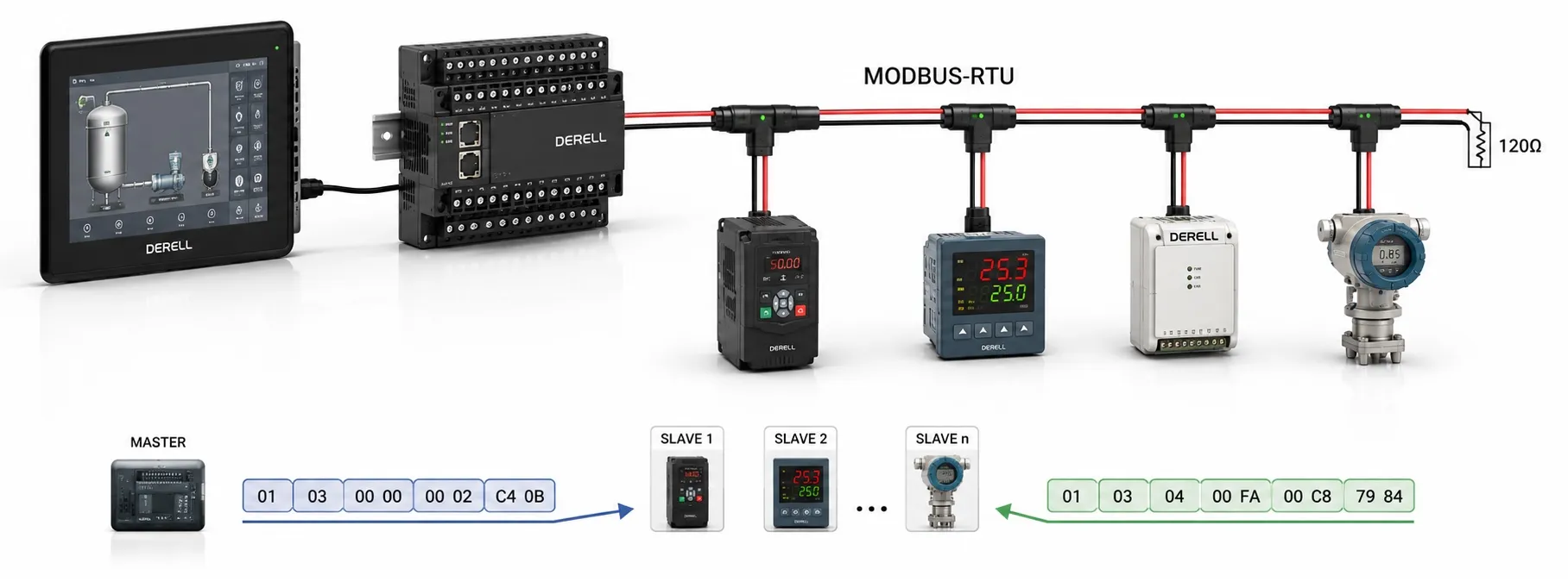
MODBUS RTU — Remote Terminal Unit is the compact binary serial transmission mode of the Modbus application protocol. It is widely used for exchanging data between PLCs, HMIs, motor drives, meters, sensors and other industrial devices. RS-485 is the most common physical interface used with Modbus RTU, although Modbus RTU and RS-485 are not the same technology.
In simple terms: a Modbus RTU client can ask another device to “read this register” or “write this value to that register.” The message contains the device address, a function code, the required data and a CRC value used to detect transmission errors.
How does MODBUS RTU work?
In traditional serial Modbus terminology, the device that starts a request is called the master and the responding device is called the slave. Current Modbus documentation uses the terms client and server. Both terminologies are still encountered because a large installed base of PLCs, drives and manuals uses the older names.
For example, a PLC can read the actual output frequency of a variable frequency drive or write a new speed reference through Modbus RTU. An HMI panel can display the same register values, while selected process information may also be transferred to a higher-level SCADA system.
What does a MODBUS RTU frame contain?
A basic Modbus RTU frame follows this structure:
[Address] [Function Code] [Data] [CRC]
Address: Identifies the server device on a serial Modbus network. Normal individual server addresses range from 1 to 247. Address 0 is reserved for broadcast operations.
Function Code: Specifies the requested operation. For example, function 0x03 reads holding registers, while function 0x06 writes one holding register.
Data: Contains information required by the selected function, such as a starting register address, number of registers or value to be written.
CRC: Cyclic Redundancy Check is a 16-bit error-detection value calculated from the preceding bytes of the RTU frame. In the transmitted frame, the low-order CRC byte is sent before the high-order byte.
Example: writing the value 555 to device address 28
Suppose we want to write decimal value 555 to protocol register address 10 in a server whose Modbus address is 28. We can use Function Code 06 — Write Single Register.
Before the CRC is added, the hexadecimal request is:
1C 06 00 0A 02 2B
1C: Device address 28 in hexadecimal.
06: Write Single Register.
00 0A: Protocol register address 10.
02 2B: Decimal value 555 in hexadecimal.
The calculated Modbus CRC is 0x3AEB. Because Modbus RTU transmits the low CRC byte first, the complete request frame is:
1C 06 00 0A 02 2B EB 3A
For Function 06, a successful server response echoes the function code, register address and written value. There is no separate generic “ACK packet” after a successful write.
Be careful with register numbering: the protocol address in this example is offset 10. Traditional documentation may show holding registers using 4xxxx-style reference numbers, while PLC or HMI software may expect zero-based, one-based or full reference-number notation. Always check how the particular software interprets Modbus addresses.
What is the difference between Function 03 and Function 06?
0x03 — Read Holding Registers reads one or more 16-bit holding registers. The request contains the starting address and quantity of registers; the response contains a byte count followed by the returned register data.
0x06 — Write Single Register writes one 16-bit holding register. When the operation succeeds, the server returns the requested register address and value in its response.
A sensor or transmitter may mainly provide readable measurement registers, while a drive or controller can provide both readable status values and writable control or parameter registers. The actual supported function codes and register map come from the device manufacturer's Modbus documentation.
Why is MODBUS RTU timing important?
Unlike Modbus ASCII, a Modbus RTU frame does not use printable start and end characters. Frame boundaries are identified through silent intervals on the serial line.
At baud rates up to and including 19,200 bit/s, a valid RTU frame should be separated from the next frame by at least 3.5 character times — t3.5. If a silent interval longer than 1.5 character times — t1.5 occurs inside a frame, the receiving device should treat that frame as incomplete.
For baud rates above 19,200 bit/s, the Modbus Serial Line implementation guide recommends fixed timing values of 750 µs for t1.5 and 1.750 ms for t3.5 to reduce implementation overhead.
MODBUS RTU serial-port settings
Devices sharing the same serial Modbus network must use compatible baud rate, parity and character-format settings. The standard RTU character is based on 11 bits per character.
With parity enabled, commonly used formats are 8E1 or 8O1: one start bit, eight data bits, one parity bit and one stop bit. Even parity is the default parity specified for Modbus serial communication.
When parity is disabled, 8N2 uses two stop bits so the RTU character remains 11 bits long. Some installed devices also permit 8N1, so real equipment settings must always be compared rather than assumed.
Why is MODBUS RTU commonly used with RS-485?
RS-485 is well suited to Modbus RTU because differential signalling provides good noise immunity and several devices can share one serial bus. Two-wire half-duplex RS-485 is especially common in industrial installations.
Modbus RTU is not limited to RS-485. Point-to-point serial systems can also use RS-232. The important distinction is that RTU defines the serial Modbus frame and timing, while RS-485 or RS-232 defines the electrical interface.
Cable distance is therefore not determined by Modbus alone. Baud rate, cable characteristics, network topology, termination, device loading and electromagnetic conditions all affect the usable distance. Statements such as “Modbus RTU always works at 1200 metres” should not be treated as universal guarantees.
What does the CRC do?
The transmitting device calculates a 16-bit Modbus CRC from the address, function and data fields and appends the result to the RTU frame. The receiver performs the same calculation on the received message.
If the calculated CRC does not match the received CRC, the frame is invalid and should not be processed as a normal Modbus request. A server receiving a frame with an invalid CRC does not return a normal Modbus response.
CRC provides error detection, not error correction. If a request is lost or discarded, timeout and retry behaviour is handled by the client implementation.
Live MODBUS RTU simulation
The simulation below demonstrates basic 0x03 Read Holding Registers and 0x06 Write Single Register requests, Modbus CRC calculation, RS-485 direction changes and the t3.5 frame interval. The R0–R15 register map is a simplified educational model rather than a specific commercial device.
Why does MODBUS RTU communication fail?
Troubleshooting becomes easier when the problem is divided into three layers: physical wiring, serial-port settings and Modbus data configuration.
On an RS-485 network, reversed differential conductors, poor topology, incorrect termination, damaged cable or excessive ground-potential differences can stop communication. Long communication cables routed directly beside motor or drive power wiring can also increase susceptibility to electromagnetic interference.
Once the physical network is correct, verify baud rate, parity, stop bits and server address. If two servers on the same serial bus have the same address, both may attempt to respond to the same request and corrupt the bus traffic.
If communication exists but the expected value cannot be read, check the function code, register offset, zero-based versus one-based addressing, data type, signed/unsigned interpretation, scaling and word order for 32-bit values.
Repeated CRC errors should not automatically be blamed on software. Electrical noise, cabling faults, mismatched serial settings or a gateway that disturbs RTU frame timing can all produce invalid CRC frames.
MODBUS RTU vs MODBUS ASCII and MODBUS TCP
Modbus RTU uses compact binary serial frames and CRC error detection. Modbus ASCII represents each byte as ASCII characters and uses LRC error checking. At the same baud rate, RTU normally carries the same Modbus information with less character overhead.
Modbus TCP transports the Modbus application protocol over TCP/IP and Ethernet. RTU silent-interval timing and serial CRC are not used in the same way on Modbus TCP. For a comparison with another Ethernet-based protocol, see EtherNet/IP vs Modbus TCP.
Practical MODBUS RTU troubleshooting checklist
1. Are both devices actually using Modbus RTU?
2. Are the RS-485 or other serial connections wired according to the device manuals?
3. Do baud rate, parity and stop-bit settings match?
4. Does every server have a unique address?
5. Is the requested function code supported by the device?
6. Has the register address been int