
How is voltage measured?
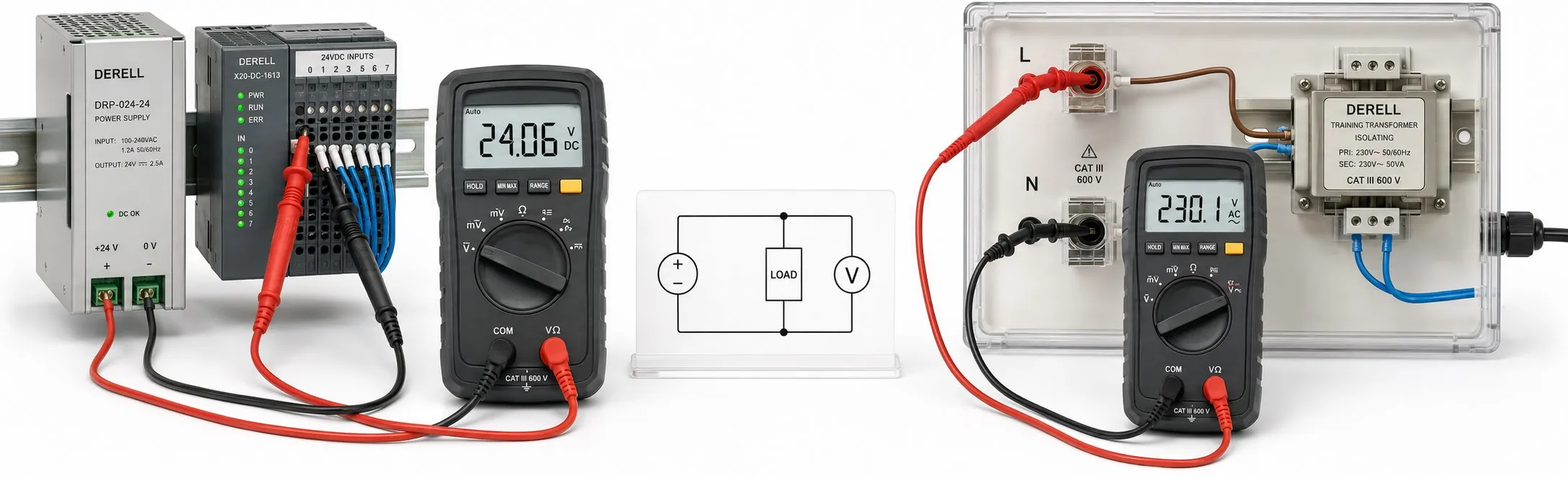
Reading the potential difference between two points
Voltage is the electrical potential difference between two points, expressed in volts. Use a multimeter in voltage mode or a suitable voltmeter. Voltage is measured in parallel: the probes touch the two points whose potential difference you want to measure. The difference between voltage and current matters here; measuring voltage does not require breaking the circuit and inserting the meter in series.
Before taking a measurement
Connect the black lead to COM and the red lead to the V input. Some meters label this shared input V/Ω. Leaving the red lead in an A or mA input and connecting across a supply can create a short circuit and cause serious damage. Do not confuse an ammeter connection with a voltage measurement connection.
Select DC V or AC V to suit the quantity being measured. Cells and many electronic power supplies provide DC voltage, while the mains supply is an AC voltage example. On a manual-ranging meter, select a suitable range above the expected value. If the value is unknown, start with the highest suitable range within the instrument’s permitted limits. Autoranging does not correct the wrong function or input connection.
A DC example using a single cell
A single 1.5 V cell can be used to learn the basic method. With the meter in DC voltage mode, place the black probe on the negative terminal and the red probe on the positive terminal. Read the voltage measured in parallel across the terminals. Although the nominal value is 1.5 V, the actual reading depends on cell chemistry, state of charge and connected load.
Reversing the probes on a digital multimeter may produce a reading such as −1.50 V. This indicates reversed polarity relative to the chosen reference; it does not by itself mean the cell is faulty. This explanation applies to a digital meter operating within its permitted voltage range; reversed polarity can have different consequences on an analog instrument.
What the diagram shows: Start moves the probes to the cell terminals. Once both contacts are made, the example 1.50 V reading appears. Stop halts the movement at its current position; Start runs the demonstration again. This is an illustration, not a measuring instrument. Moving the probes closer does not increase cell voltage. Reduced-motion mode displays a stationary connection.
Editor’s note: COM is the meter’s common reference input; it is not necessarily protective earth. A cell’s negative terminal, circuit 0 V and protective earth share a reference only when connected by the circuit design. The black probe’s location determines what the displayed value means.
AC measurements, RMS and waveform shape
An AC voltage reading is usually interpreted as an RMS value. An average-responding meter calibrated for sine waves can give incorrect results on distorted waveforms. True RMS addresses this limitation, but the meter’s frequency bandwidth, crest factor and input limits still apply. A True RMS label alone is insufficient without considering frequency and waveform shape.
On many meters, AC mode measures only the AC component; combined AC+DC RMS may require a separate function. Ordinary AC measurements can be misleading on PWM drive outputs; use the manufacturer’s specified instrument, filter or measurement method. If an oscilloscope is needed to inspect the waveform, its probe voltage rating, isolation and reference arrangement must be suitable. An earth-referenced probe clip must not be connected to an arbitrary circuit point.
Interpreting the result
Record the measurement points and load condition together. For example, if the source reads 24.1 V and a remote load input reads 21.8 V under the same operating conditions, the difference is 2.3 V. This provides a starting point for investigating voltage drop in wiring and connections. Low voltage can also originate in the supply itself; one reading does not conclusively identify a faulty component.
Unconnected probes do not necessarily produce a 0.00 V reading. High input impedance can allow surrounding electric fields or ghost voltage to influence the display. A suitable meter’s LoZ function can help distinguish some cases, but its greater circuit loading makes indiscriminate use unsuitable for sensitive electronic nodes. Do not dismiss an unexplained reading as harmless interference without checking it.
If OL or an overrange indication appears, check the range, function and manufacturer’s explanation; the indication does not mean the same thing on every instrument. More display digits do not automatically mean greater accuracy: consider measurement error, resolution and calibration together. Brief voltage fluctuations may be missed by the normal display if the instrument’s capture speed is insufficient.
Essential safety distinctions
Mains and industrial panel measurements require qualified personnel, suitable procedures and appropriate protective equipment. Both the meter and probes need a CAT category and voltage rating suitable for the measurement location. Inspect insulation and probe tips before use. The highest number the meter can display does not establish that it is safe for that environment.
Do not use resistance or continuity mode on an energized circuit. Before measuring resistance, disconnect the supply and address stored energy using an appropriate method. When verifying absence of voltage, check the suitable test instrument against a known source or proving unit before and after the test. A single zero reading can also result from an incorrect setting or instrument failure. Electric shock and arc risks cannot be assessed from nominal voltage alone.
Related topics: Low-voltage hazards, high voltage and its risks.
Sources
Fluke: DC voltage measurement, input jacks and polarity
HIOKI: measurement categories and incorrect connections
Keysight: True RMS, waveform shape and AC component measurement
HIOKI: ghost voltage and the principle of LoZ measurement
Megger: instrument safety and verifying absence of voltage
Keysight: parallel measurement, input impedance and accuracy