
Flat-head vs. protruding-head sensors
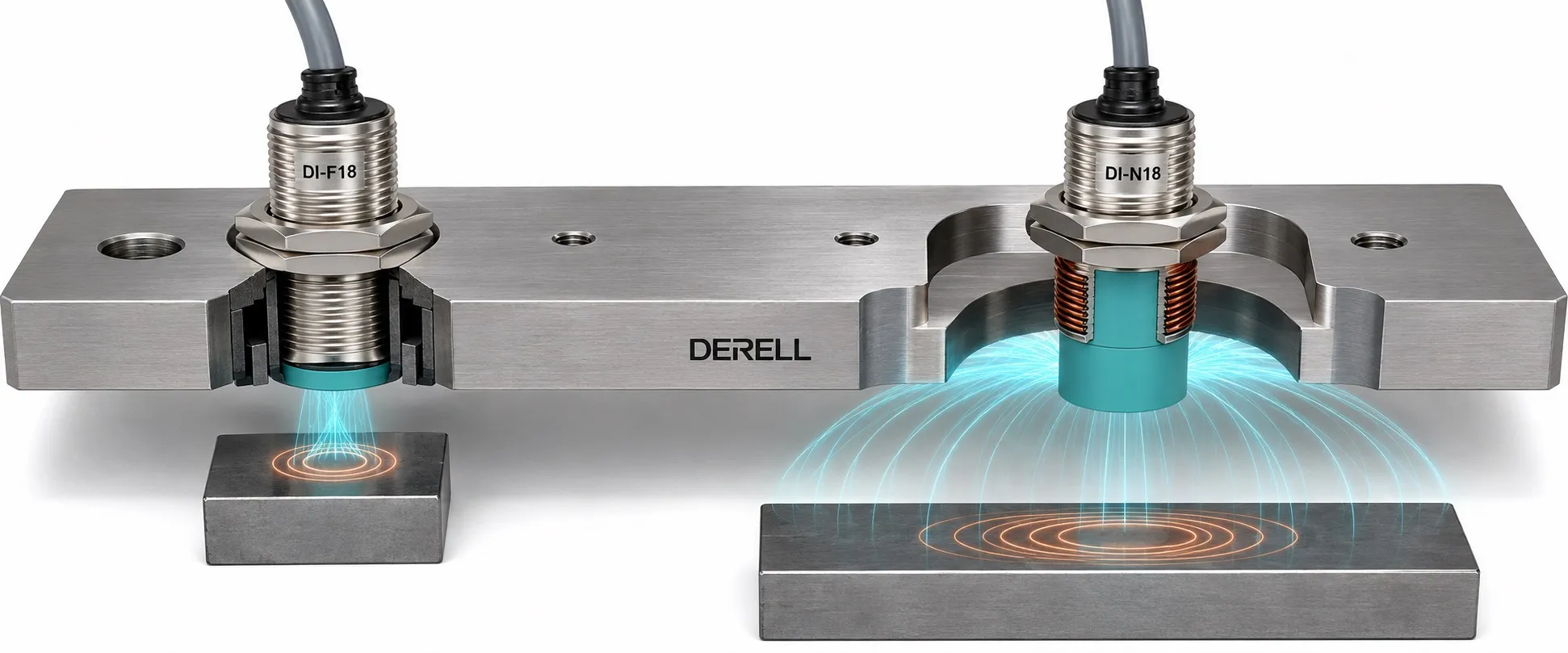
Flush vs non-flush inductive sensors: start with the mounting
Flush and non-flush describe installation requirements, not simply the shape of a sensor tip. A flush-rated inductive sensor can sit level with surrounding metal under its specified conditions. A non-flush model needs the required metal-free clearance around the active end. Check the mounting drawing, not just the product photograph. [1]
Both designs detect the influence of a metal target on the field generated by the sensor. Their coil, oscillator and evaluation circuit perform non-contact detection. This choice is separate from PNP/NPN output configuration and NO/NC behaviour. [6]
What shielding changes—and what it does not
Shielded sensors restrict the field around the sides of the sensing coil, concentrating it towards the face. That permits suitable metal-embedded installation. It does not mean that you can put a metal cover across the active face, and sensor shielding is not the same specification as cable shielding. [1]
The mechanical benefit comes from keeping the sensing end within the outline of its support, reducing its exposure to accidental contact. That is not permission to use it as a mechanical stop. A workpiece should be arrested by a suitable mechanical arrangement, not by hitting the sensor.
Non-flush designs commonly offer more range than comparable conventional flush designs, but need more consideration of nearby metal. The projecting sensing end also needs mechanical protection. The extra reach is useful only when the required installation clearance is available. [2]
Practical selection: When a metal pocket must surround the sensor up to its face, begin with an appropriate flush model. When clearance is available and extra reach matters, consider non-flush options. Use the sensor-type guide and detection-method comparison to define the job before choosing a housing.
Compare the same target gap, not the same bracket position
The two scenes use illustrative detection limits of 5 mm and 8 mm. Each target moves through gaps of 10 mm → 6 mm → 3 mm → 10 mm, measured from its own sensing face. At 6 mm only the example non-flush device detects the target; at 3 mm both do.
Start restarts the corresponding scene; Stop freezes its current frame. Grey blocks represent mounting metal and pale shapes suggest field spread. This is a teaching sequence, not a product test or field calculation. Tolerance and hysteresis are not modelled, and no installation dimensions should be taken from the drawing.
Keep three different clearances separate
Clearance around the active end: A non-flush nose must not be enclosed by mounting metal, nuts or clamps contrary to its drawing. Check the required projection and lateral spacing. Unwanted fixed metal in front also matters. A front clearance requirement does not prohibit the intended target from entering the sensing area. [3]
Spacing between sensors: Side-by-side and face-to-face installations can require different distances. Confirm whether a dimension means an edge-to-edge gap or centre spacing. Do not assume one housing diameter always prevents interference; use the selected model’s installation table. [3]
Why M12, M18 and M30 do not specify the range
Conventional examples in the Pepperl+Fuchs installation guide give 2 / 4 mm for M12, 5 / 8 mm for M18 and 10 / 15 mm for M30, in flush / non-flush order. They are not universal range limits. Extended-range and semi-flush designs need their own assessment. [2]
Rated operating distance Sn is not an installation allowance covering all production tolerances, supply changes and temperature effects. Compare the complete inductive sensor specification, including model suffix, usable range and mounting restrictions. The inductive sensor standards guide explains the terminology. [5]
The usual relationship for assured operating distance Sa, with the standard target and stated conditions, is 0 < Sa ≤ 0.81 × Sn. For an Sn of 5 mm, this gives 4.05 mm. It is not an automatic guarantee for a different target, nor a machinery-safety approval. [4]
Material and target size still count
A steel reference does not establish the same range on every metal. Correction factors are sensor-specific, and a small target needs separate evaluation. Specify the alloy and coating, not just “chrome”. Do not apply one universal factor to stainless steel, aluminium and targets of different thicknesses. [4]
Illustrative calculation: Suppose the specified correction factor for a particular target is 0.6 and the steel-reference range is 5 mm. Applying only that factor gives 5 × 0.6 = 3 mm. The calculation includes no additional allowance for vibration, tolerances or target size. It is a preliminary comparison, not a mounting setting.
Replacing a sensor means checking more than the threaded barrel
Electrical match: Confirm the PLC input, supply, PNP/NPN output, NO/NC logic and cable or connector pinout. A conventional two-wire sensor is not the same interface as NAMUR. The mechanical mounting class does not establish electrical compatibility. [7]
Timing and environment: Check switching frequency, target dwell time, temperature limits and the IP rating. Apply the specified tightening torque and use suitable mounting accessories. Read the terminology associated with IEC 60947-5-2 alongside the individual product limits. [5]
A useful troubleshooting sequence: A sensor that works away from the bracket but stays actuated after installation deserves a mounting check before replacement. With the machine made safe and the target removed, inspect nearby metal, the clamping position and accumulated swarf. Then compare the sensor indication with the controller input. Isolate safely before altering connections or mechanical settings, and prevent unexpected movement.