
What is the adjustable temperature range?
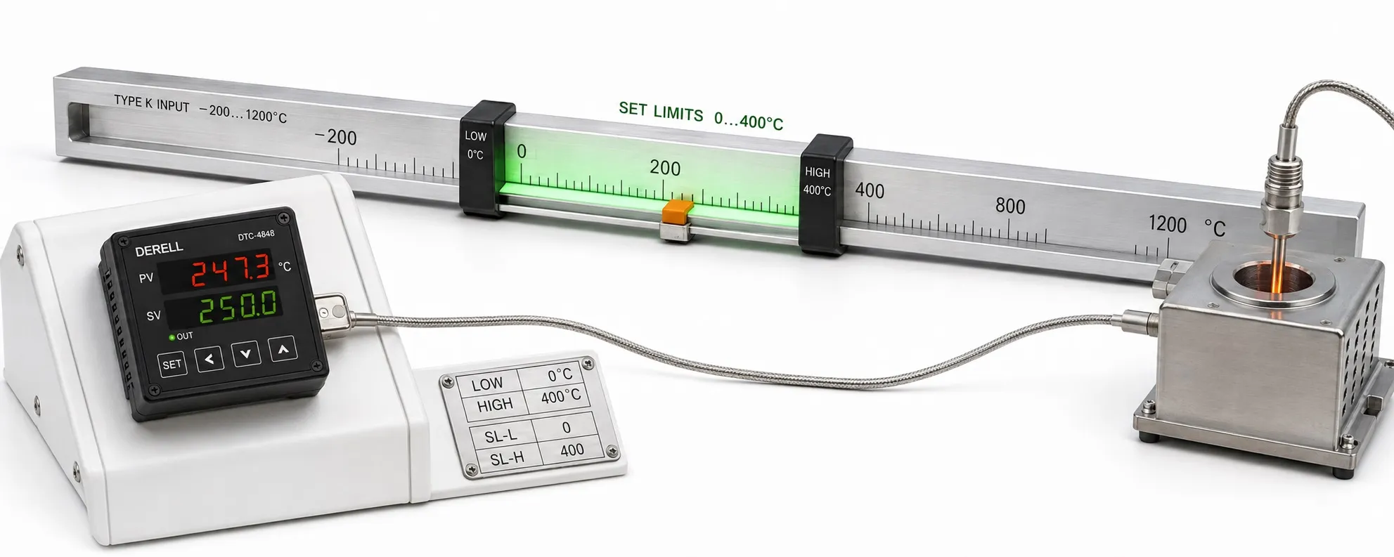
An adjustable target is different from a verified operating limit
Hello, a temperature controller's adjustable temperature range describes the lower and upper limits between which an operator can select the target. It depends on supported inputs, the selected sensor, scaling and setpoint limits. Being able to enter a value does not establish that the machine can reach it or operate there safely.
Editor's note: Measurement range, setpoint limits, probe rating and process capability are separate specifications. A controller capable of measuring high temperatures may be connected to a probe with a much lower cable or assembly limit. Do not treat the largest catalog number as the operating temperature of the entire system.
One instrument can have several different ranges
The input/measurement range defines the values that can be measured for the selected signal; maximum temperature capability belongs in this category. The setpoint range defines permitted target selection. The display scale maps an input signal to engineering units, particularly for analog inputs. These do not necessarily share identical endpoints.
The probe operating range depends on the sensing element, sheath, connection head, seals and cable. The validated process range concerns what the machine can achieve under load. The controller's ambient temperature limit is separate: measuring 500 °C does not mean its electronics can operate in a 500 °C environment.
Sensor selection changes the available range
Thermocouple, RTD and thermistor inputs do not use one interchangeable range table. Selecting a K, J or T thermocouple, Pt100 or another RTD can change the available input range. Universal input does not mean support for every sensor and temperature. Use the exact model's input table and selected measurement curve.
A “Pt100” or “type K” label alone does not establish the complete probe's temperature rating. Identical sensing elements can have different assembly limits when supplied with different sheaths and cables. During installation, consider which probe sections enter the hot zone; a suitable measuring tip does not establish that its connection cable can withstand the same temperature.
How do lower and upper setpoint limits work?
Many controllers provide lower/upper setpoint limits to restrict operator target selection. If a process is to operate between 80 and 160 °C, its operator range can be narrowed accordingly even when the instrument supports a much wider input range. This does not change the input hardware or physical sensor rating. During controller selection, distinguish this function from measurement capability.
| Manual / series | Lower setpoint limit | Upper setpoint limit |
|---|---|---|
| Eurotherm 3100/3200, HA028651 Issue 7 | SP.LO | SP.HI |
| Autonics TK, communication manual | L-SV | H-SV |
| OMEGA manual M4496 | SPLO | SPHI |
These parameter names are examples. Access levels, underlying input restrictions and the setpoints affected depend on the model. A setpoint limit, high-temperature alarm and independent overtemperature shutdown are different functions. Limiting the target to 160 °C does not make a failed SSR disconnect power.
Combining four limits in one example
Entirely hypothetical example: The selected input measures −200…850 °C, the complete probe is rated for −50…250 °C, the validated machine range is 60…180 °C, and the permitted operator target is 80…160 °C. Select the operating target within 80…160 °C; the 250 °C probe limit and 850 °C input capability do not extend that permission.
Allowing a 170 °C target in this example requires more assessment than changing a menu value. Review product limits, overshoot, alarm thresholds and approved operating conditions. The sensor must also measure actual temperature correctly; an overlap between written ranges does not by itself guarantee control performance.
4–20 mA scaling does not change temperature capability
If a transmitter is configured for 4 mA = 0 °C and 20 mA = 400 °C, configure matching endpoints in the controller. Here, 12 mA = 200 °C. If the controller is incorrectly scaled to 0–200 °C, the same 12 mA displays as 100 °C; the actual process has not become cooler.
For this linear example, T = Tlow + [(I − 4) / 16] × (Thigh − Tlow), with I in mA. This applies to a correctly scaled 4–20 mA temperature signal. Do not apply the same linear current calculation to a direct thermocouple or RTD input. Verify transmitter range, input scaling and setpoint limits together.
The machine must also have sufficient capacity
Heater capacity and heat losses affect whether the target can be reached, but are different from the software setpoint range. An underpowered furnace does not reach 250 °C under load merely because 250 °C can be selected. Assess power and energy requirements together with process load and losses.
Likewise, entering a 10 °C target does not create active cooling in a resistance-heated system operating in a 25 °C environment. Thermal inertia and delays and the heating/cooling control method govern actual behavior. Evaluate the time needed to reach the target separately as part of response time.
A wide range does not mean identical accuracy throughout
A 0.1 °C adjustment step or display resolution does not guarantee ±0.1 °C overall accuracy. Measurement accuracy may involve a percentage of reading, full scale/configured span, extra digits, sensor tolerance and environmental effects. Selecting a narrow target band does not automatically reduce these error terms.
If accuracy depends on configured span, check how scaling changes affect it; controllers do not all behave identically. PID tuning may also need review because load and heat transfer can vary across the range. Target range and output cycling are different concepts; cycle time is a separate control parameter.
Why can the required target not be entered?
First check lower/upper setpoint limits, selected input, °C/°F units and parameter locks. A remote target or program segment may be active instead of the local target. For targets written through communications, register scaling, write permissions and accepted limits also matter. Do not assume every model handles front-panel and communication commands identically.
If a value is rejected or an out-of-range message appears, do not select an arbitrary sensor type to bypass the restriction. Incorrect input selection can produce plausible but false temperatures. During fault investigation, assess the input table, active target source and limit parameters together.
Verify limits for ramps, programs and remote targets
With ramp/soak functions, target temperature, target ramp rate and soak conditions are separate settings. A “2 °C/minute setpoint ramp to 120 °C” does not mean the process heats at exactly that rate under all conditions. Heater capacity and control behavior affect the result; some controllers can delay soaking until a specified tolerance condition is met.
Check which limits apply to local targets, alternative targets, recipe segments and remote targets. Program limits, alarm thresholds and safety shutdown do not replace one another. Also establish which target becomes active after a power interruption.
What should be checked after changing a range?
Back up parameters before changing them, recording sensor selection, scales, setpoint limits and alarm settings. Verify operating points against a suitable reference while maintaining the required protection and environmental conditions. Review related parameters particularly carefully after changing °C/°F units, transmitter scaling or sensor type.
A commissioning record should contain more than “range 0–400 °C.” Record the input type/range, probe limits, permitted operator target band, validated process limits and alarm/shutdown conditions separately. During maintenance and later modifications, this record helps prevent inappropriate expansion of the operating range.
Related products and technical guidance
Controllers and sensors: Temperature controllers, temperature controller prices, temperature sensors.
Control and tuning: PID temperature control, PID gain adjustment, conditions for stable control.
Processes and further questions: PID tuning for different processes, temperature controller questions and answers.
Sources
Eurotherm — 3100/3200 Engineering Manual: Setpoint Limits and Scaling
OMEGA — M4496: Input Configuration, Scaling and Setpoint Limits
Autonics — TK Series: L-SV/H-SV and Input Scaling Parameters
WIKA — RTD vs. Thermocouple Temperature Sensors
WIKA — Pt100 Wiring and Lead Resistance
NI — PID Theory: Process Response, Delay and Tuning
OMRON — Temperature Controller Safety Precautions
OMEGA — Platinum Series: Sensor Inputs, Resolution and Profiles