
How is the temperature control cycle set?
Start by identifying which timing parameter you are changing
Hello, setting up a temperature controller involves matching its sensor input, control method, output behaviour and PID parameters to the application. However, input sampling time, PID calculation interval and output switching period describe different things. Check the manual for the specific product to establish what its “cycle time” parameter actually controls.
Sampling, calculation and switching are different
Sampling time describes the interval between input measurements. On many panel controllers, it is set by the manufacturer and may not be user-adjustable. The system's overall response time to a temperature change also depends on sensor thermal lag, input filtering and process behaviour.
The PID calculation interval determines how often the algorithm calculates a new output demand. It may match the sampling interval, but this should not be assumed for every controller. The output period is the repetition time of the switching pattern in time-proportioning control. Reducing it does not automatically increase the sensor sampling rate or make a furnace heat up faster.
Editor's note: Fast input measurement does not mean a mechanical relay should switch at the same rate. Assess the electronics' measurement speed separately from the switching limits of the power device.
What does the output period mean in practice?
For fixed-period time-proportioning control, a 10-second period at 30% output demand gives a simplified pattern of 3 seconds on and 7 seconds off. With a 2-second period, the same ratio becomes 0.6 seconds on and 1.4 seconds off. These are calculation examples, not recommended settings. Minimum on/off times and the manufacturer's output algorithm may change the actual pattern.
At the same duty ratio, a shorter period does not by itself change the average power of an ideal constant-power heater; it changes how that power is distributed over time. A shorter period should therefore not automatically be interpreted as energy savings.
Relay, SSR and analogue outputs need different treatment
For a mechanical relay or contactor, an excessively short period increases switching operations and wear. An SSR may support more frequent switching, but the load, power unit and manual limits still matter. A 4–20 mA or 0–10 V output sends a proportional command to a power unit, so the same on/off period approach may not apply directly. Check the wiring and output configuration accordingly.
For compressor cooling, preserve the manufacturer's minimum run and restart times. Do not transfer a fast heater-switching pattern to a compressor. Where heating and cooling outputs are provided, assess their settings separately.
What is a sensible commissioning sequence?
Record the existing settings first. Check the sensor type, wiring, °C/°F units and measurement accuracy. Do not attempt to compensate for the wrong sensor configuration by tuning PID. Then verify the setpoint and setting limits, output type and control direction: for heating, a temperature below the setpoint should generate heating demand. Interpret “direct/reverse” labels using the product manual.
Choose ON/OFF or PID control to suit the process. With ON/OFF control, hysteresis is a key setting, and the definition of the switching thresholds depends on the model. With PID, the proportional, integral and derivative parameters are adjusted. The output period does not replace these parameters.
Do not copy PID numbers between controllers
Some controllers use proportional gain, while others use proportional band; their adjustment directions differ. Likewise, integral time (Ti) differs from integral gain (Ki). For the same algorithm with other conditions unchanged, increasing Ti slows integral action, whereas increasing Ki strengthens it. Check seconds versus minutes and the parameter definitions before transferring settings.
When should auto-tuning be used?
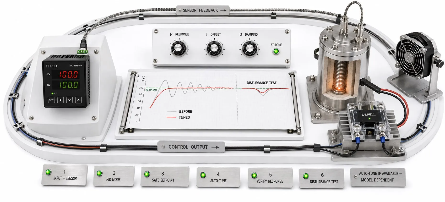
If supported, auto-tuning can help establish starting PID settings. Verify the sensor, output and control direction first, then follow the manufacturer's specified starting conditions. Output demand and temperature may vary during tuning, and the product must tolerate those variations. Successful completion does not guarantee stable control under every load.
After tuning, observe overshoot, oscillation, settling time and steady-state error. Test warm-up and normal load changes. Allow enough time to understand each adjustment, and avoid changing several parameters at once. Recording data through communications makes it easier to review temperature and output demand together.
Look beyond PID when troubleshooting
If temperature oscillates, also investigate sensor placement, delays, excessive filtering, inadequate heater capacity and output problems. Maintenance issues and unsuitable cabinet conditions can affect the result. If heating continues despite an off command, investigate a power-circuit fault rather than changing PID settings.
PID tuning is not a safety safeguard. Where hazardous overheating is possible, independent limit protection must be able to interrupt the hazardous energy flow independently of normal control. Restricting the setpoint or displaying an alarm does not provide that function by itself.
When selecting a controller, assess its sensor inputs, output hardware, available timing settings and process requirements alongside its PID capability. There is no universal P, I, D or output-period setting without knowing the controller model and load.
Temperature controllers | Temperature controller FAQ | Temperature controller prices