
Can you provide information about the device's fault detection and error codes?
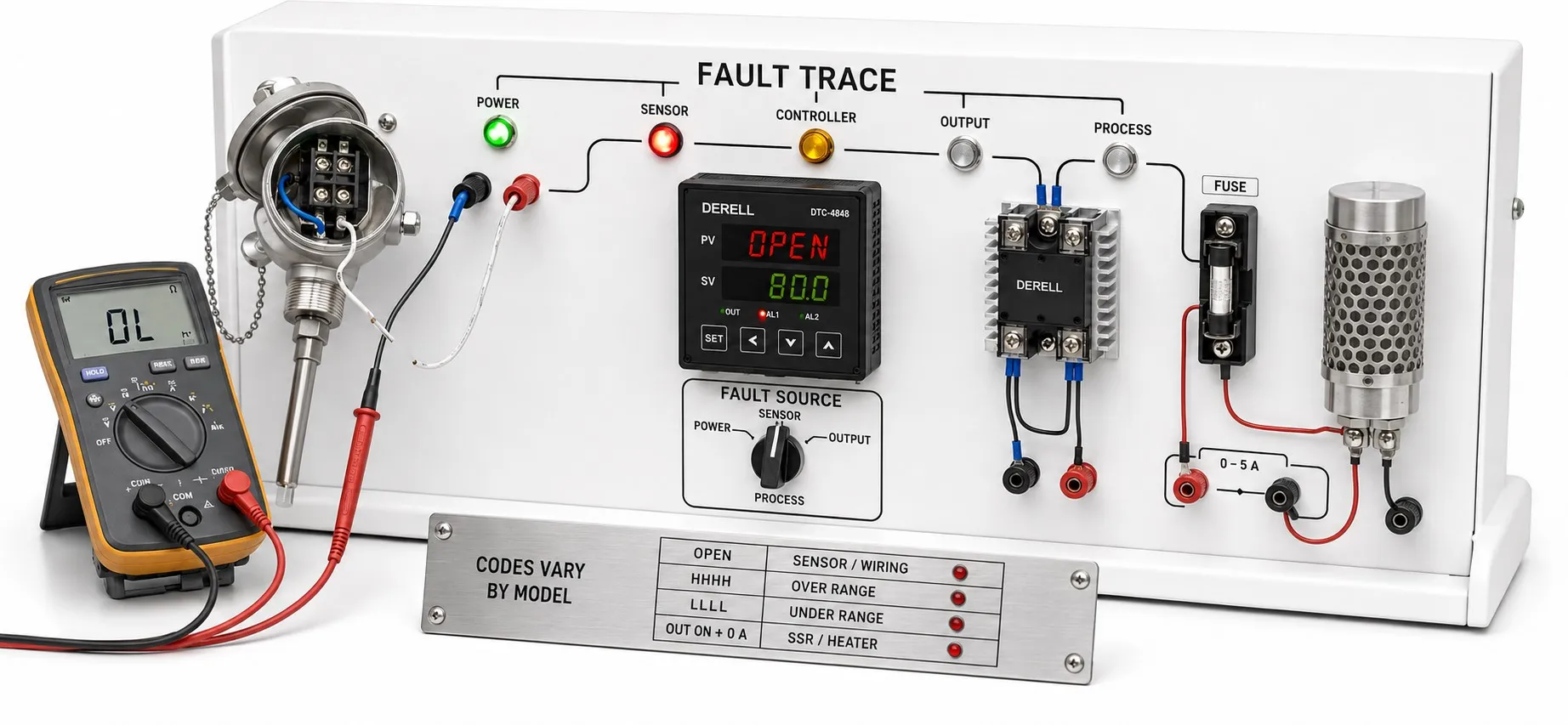
Assess the message, measurement and actual load behavior together
Hello, troubleshooting a temperature controller involves four separate points: sensor measurement, controller demand, power-circuit operation and process response. A displayed code may identify part of this chain; it does not necessarily identify the component to replace. Not every controller monitors load current, supply voltage or relay health.
Editor's note: E1, E2, ERR and similar indications are not universal error codes. The same display can mean different things across manufacturers. Interpret a code using the complete model, manual revision and configured input type. Absence of an error message does not prove that the sensor and power circuit are healthy.
Make the process safe, then preserve the evidence
If temperature rises uncontrollably, do not rely solely on a stop command in the display menu; follow the plant's appropriate isolation and safe-shutdown procedure. Perform wiring and installation inspections after isolating energy sources and verifying absence of voltage. Energized measurements require appropriate competence and suitable measuring arrangements.
Before resetting, record the code, measured PV, target SV, output percentage and indicator states. Note whether the fault occurs at startup, after warming up or when a contactor operates. A factory reset without a parameter backup can change the input type, output assignment and alarm limits, making diagnosis more difficult.
Verified examples: Keep each code in its own context
| Manufacturer / scope | Indication | Meaning in this context |
|---|---|---|
| OMRON temperature-controller technical guide | S.Err | Investigate the input/measurement chain. Possible causes include incorrect input selection, an incompatible sensor or wiring problems. It does not prove that the sensor itself has failed. |
| Eurotherm 3100/3200, HA028651 Issue 7 | S.br | Sensor-break alarm associated with an open sensor or open wiring between sensor and controller. Output behavior depends on the configured safe output value. |
| Autonics TK, Modbus communication manual | 01 | Modbus exception response: unsupported function. This is not a temperature fault indication on the front panel. |
| Autonics TK, Modbus communication manual | 02 / 03 | 02: invalid data address. 03: invalid data value. Check the register address and requested write value. |
This is not a universal code list. Labels such as AL1/AL2 also commonly identify alarm channels or output states; configuration determines whether the assigned condition is high temperature, deviation or another function.
An open sensor and a short circuit may behave differently
A broken lead, loose terminal or incorrect connection can produce an input error. First verify sensor/input compatibility and thermocouple polarity. A shorted thermocouple cable can create a measuring junction at the wrong location; the controller may show a plausible low temperature and continue heating. “No error code” is therefore insufficient evidence.
For Pt100 wiring, the two-/three-/four-wire arrangement and terminal assignment matter. Unequal lead resistances can introduce error in a three-wire measurement. Perform resistance and continuity checks with power isolated and the measured circuit appropriately disconnected from the controller input. Bridging a sensor input is not a repair.
An out-of-range indication does not always mean actual overheating
A high/low range indication can result from a genuine temperature excursion, an incorrect sensor selection or signal-scaling errors. Check the maximum input capability separately from the setpoint/scaling range. A 4–20 mA transmitter introduces its own supply and possible faults into the measurement chain.
Even a normal-looking reading may be shifted by an incorrect °C/°F setting, offset or transmitter scale. Assess measurement accuracy using a suitable reference and measurement location. A sensor detached from the product may measure ambient temperature while the controller appears operational and the product overheats.
The OUT indicator is on, but there is no heating
The OUT indicator generally shows command status, not proof of load current. Establish whether the output is an SSR drive signal, relay contact or analog demand and whether it matches the external circuit. A competent investigation then separates the load supply, protective devices, contactor/SSR and heater circuit.
For example, if PV is 25 °C, SV is 180 °C and heating demand is high without a temperature rise, changing PID settings is not the right starting point. Possible causes include an open heater, missing load supply or a command not reaching the power device. Load-current diagnostics require suitable CT hardware/input and correct thresholds; they are not automatically available on every controller.
The OUT indicator is off, but temperature is rising
An initial rise may result from stored heater energy continuing to reach the product. Distinguish thermal inertia from continuing electrical heating; process delay matters here. A shorted SSR or welded contactor, however, can continue delivering energy despite an off command.
Do not spend time tuning PID during a dangerous temperature rise. Depending on application risk, provide an independent overtemperature limiter with its own sensor and suitable power disconnection. The controller's alarm indicator may not physically disconnect a failed power device. Loss of cooling or heat generated by the process itself must also be considered.
Oscillation and overshoot are not always electronic faults
An unsuitable ON/OFF or PID mode, aggressive integral action, inappropriate output cycle time, sensor position or changing load can cause cycling. Separate common PID problems from hardware failures. Derivative action is sensitive to noisy measurements, while stronger filtering can increase delay.
Where available, loop-break detection can alarm when the expected process response fails to occur. This does not directly mean that a sensor wire is broken; insufficient power, incorrect control direction or unsuitable timing also require investigation. Use auto-tune only after verifying the measurement and power circuits, under conditions the process can tolerate.
Distinguish no communication response from an exception response
For RS-485/Modbus troubleshooting, check device address, baud rate, parity, wiring arrangement and register map. No response differs from receiving a valid exception response. For example, exception 02 points toward addressing; it does not, by itself, justify replacing the controller.
If a value is returned but appears incorrect, check decimal scaling, signed/unsigned interpretation and, where applicable, multi-register data order. The Autonics TK map assigns some PV values to special input states rather than normal temperatures. Do not convert a raw register value into degrees without checking its format. Do not assume communication loss stops the output: continued local control or use of the last setpoint depends on the model.
A blank display, repeated restart or internal error
A blank display can result from absent external power, the wrong supply version, connection problems or an internal hardware fault. Not every device provides a separate “PSU” code for low/high voltage. For restarts occurring after warming up, assess ambient temperature and humidity, supply conditions and interference together.
For moisture, condensation and contamination, establish which surfaces the protection rating covers. Follow the exact model's instructions for memory or A/D-converter errors. Repeated internal faults call for service investigation, with the code, conditions and configuration supplied to the manufacturer, rather than repeated resets.
After repair, verify more than disappearance of the code
After correcting wiring or replacing a component, verify measurement, control direction, alarm limits, power-restoration behavior and load disconnection under controlled conditions. Maintain the required electrical safety conditions. Alarm acknowledgement may only accept the notification; it does not remove the cause.
Service record: Capture the brand and complete model, code photograph, PV/SV, input/output types, supply, fault timing and recent changes. If replacement is necessary, use this information for controller selection. Matching bezel dimensions or a PID label does not establish interchangeability.
Related products and troubleshooting guidance
Controllers and sensors: Temperature controllers, temperature controller prices, temperature sensors.
Control behavior: Response time, PID gain adjustment, using PID for temperature control.
Further technical questions: Power consumption and energy efficiency, temperature controller questions and answers.
Sources
OMRON — Temperature Controllers: Troubleshooting and Further Information
Eurotherm — 3100/3200 Engineering Manual, HA028651 Issue 7
Autonics — TK Series Communication Manual
OMRON — SSR Failure Causes and Protective Measures
OMRON — Temperature Controller Safety Precautions
WIKA — Pt100 in 2-, 3- or 4-wire connection?
NI — PID Theory: Noise, Delay and Control Response
Eurotherm — Principles of PID Control and Tuning
Modbus Organization — Serial Line Specification and Implementation Guide